

Learn the basics of centrifugal pumps, how they work, the different types and where we use them.
Scroll to the bottom to watch the YouTube tutorial.
State Supply is your source for steam and hydronic heating system components, such as steam traps, valves, controls, and pumps (including the industry’s top brand like Bell & Gossett, Taco, and more). Visit www.statesupply.com or call us toll-free at 877-775-7705 for an unparalleled selection of products, knowledgeable experts, and outstanding customer service.
Check out centrifugal pumps ➡️ https://www.statesupply.com/pump/hydronic
View pump repair & maintenance videos ➡️ https://www.youtube.com/statesupply
Download this guide ➡️ https://www.statesupply.com/boiler-inspection-checklist
What Does a Centrifugal Pump Look Like?
Centrifugal pumps come in many shapes, colours and sizes but they typically look something like this.
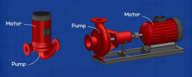
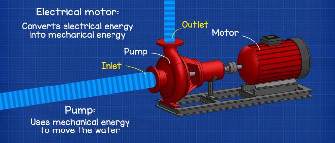
The pumps consist of two main parts, the pump and the motor. The motor is an electrical induction motor which allows us to convert electrical energy into mechanical energy. This mechanical energy is used to drive the pump and move the water. The pump pulls water in through the inlet and pushes it out through the outlet.
Inside a Centrifugal Pump
As we take the unit apart, we can see that we have a fan and protective casing mounted at the back of the electrical motor. Then inside the motor we have the stator, mounted to the motors casing, which holds the copper coils, and we’re going to look in detail at that a little later in this video. Concentric to this we have the rotor and shaft. The rotor rotates and as it rotates so does the shaft. The shaft runs along the entire length from the motor and into the pump. This then connects onto the pumps impeller. Some models of centrifugal pumps, like this one, will have a separate shaft for the pump and the motor. Separated shafts are joined using a connection known as a coupling. Coupled pumps will usually have a bearing house which, as the name suggests, houses the bearings.
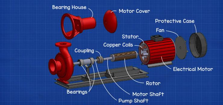
The shaft continues into the pump casing. As it enters the casing it passes through a gland, packing and the stuffing box which combine to form a seal. The shaft then connects onto the impeller.
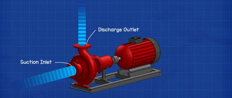
The impeller imparts a centrifugal force onto the fluid which enables us to move liquids, such as water, through a pipe. The impeller is enclosed within the pump casing. The casing contains and directs the flow of water as the impeller pulls it in and pushes it out. Therefore we have a suction inlet and a discharge outlet.
How Does The Centrifugal Pump Work?
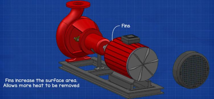
At the back of the electrical motor, we see that the fan is connected to the shaft. When the motor rotates the shaft, the fan will therefore also rotate. The fan is used to cool down the electrical motor and it will blow ambient air over the casing to dissipate the unwanted heat. If the motor becomes too hot, the insulation on the coils inside the motor will melt causing the motor to short circuit and destroy itself. The fins on the outside perimeter of the casing increase the surface area of the casing which allows us to remove more unwanted heat.
The electrical motor comes in either three phase or single phase configuration, depending on the application.
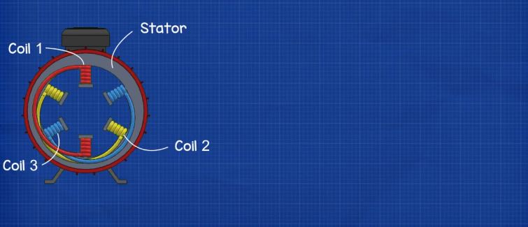
We’re going to look at three phase as it’s the most common. Inside the 3 phase induction motor we have 3 separated coils which are wound around the stator. Each coil set is connected to a different phase to produce a rotating magnetic field.
When we pass AC, or alternating current, through each coil, the coil will produce an electromagnetic field which changes in intensity as well as polarity as the electrons passing through it change direction between forwards and backwards.
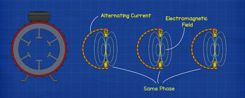
But, if we connect each coil to a different phase, then the electrons will change direction between forwards and backwards at different times compared to the other phases. This means that the magnetic field of each coil will change in intensity as well as polarity at different times compared to the other phases.

To distribute this magnetic field, we rotate the coils 120 degrees from the previous phase and insert them into the stator of the motor casing. This will create the effect of a rotating magnetic field. At the centre of the stator we place the rotor and shaft. The rotor will be affected by the rotating magnetic field and will force it to also rotate.

The rotor is connected to the shaft and the shaft runs from the fan, through the rotor, all the way up to the impeller. This way when the rotor rotates, so will the impeller. So now, by creating the rotating magnetic field within the motor, we spin the rotor which spins the shaft and this spins the impeller.
Looking at the pump casing, we find a channel for water to flow along which is called the volute. This volute spirals around the perimeter of the casing up to the pump outlet, this channel increases in diameter as it makes it way to the outlet.

The shaft passes through the seals and into the pump casing where it connects to the impeller.
There are many types of impeller but most will have these backwards curved vanes which will either be open, semi open or closed in with some shrouds.

These backwards curved vanes do not push the water. The curves rotate, with the outer edge moving in the direction of the expanding volute. These vanes will provide the fluid with a smooth path for the water to follow. We’ll see that a little later in the video.
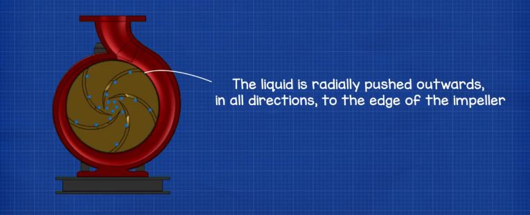
The impeller is submerged in water. When the impeller rotates, the water within the impeller will also rotate. As the water rotates, the liquid is radially pushed outwards in all directions to the edge of the impeller and into the volute. As the water moves outwards off the impeller it creates a region of lower pressure which pulls more water in through the suction inlet. The water enters into the eye of the impeller and is trapped between the blades.
As the impeller rotates it imparts kinetic energy, or velocity, onto the water. By the time the water reaches the edge of the impeller it has reached a very high velocity. This high speed water flows off the impeller, and into the volute, where it hits the wall of the pump casing. This impact converts the velocity into potential energy or pressure. More water follows behind this and so a flow develops. The volute channel has an expanding diameter as it spirals around the circumference of the pump casing. As it expands, the velocity of the water will decrease resulting in the pressure increasing. This expanding channel therefore allows more water to keep joining and converting into pressure.
So the discharge outlet is therefore a higher pressure than the suction inlet. The high pressure at the discharge allows us to force the fluid through pipes and into a storage tank or around a pipe system.

The thickness of the impeller and the rotational speed affects the volume flow rate from the pump but the diameter of the impeller and the rotational speed will increase the pressure it can produce.
NPSH
A term you’re going to hear is NPSH which is the acronym for Net Positive Suction Pressure. We’ll briefly cover what this means.
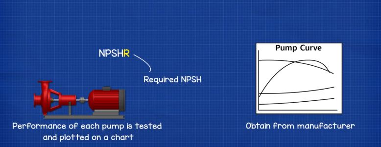
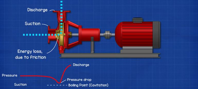
There are two letters at the end of this acronym the NPSHR and the NPSHA. The R is the required NPSH. Each pump is tested for this value and this can be obtained from the pump manufacturer via the pumps operating chart. Don’t worry about this confusing looking chart at this point, we’re going break it down and cover that in detail in a dedicated article. The R value is basically a warning or danger point. As water enters the pump and flows into the impellers eye it experiences a loss of energy due to friction, this gives us a pressure drop. At certain conditions the water flowing through this section can reach boiling point, when this occurs we refer to this as cavitation. We’ll see more on that in just a moment.
The other letter was the A and this is the NPSH available. This depends on the installation of the pump and needs to be calculated. It considers things such as installation type and elevation, liquid temperature, liquid boiling point etc.
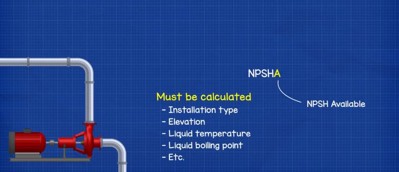
The available value should be higher than the required value. (NPSHA > NPSHR)
For example if we have an installation and we calculate the NPSHA is 11 but the pump requires an NPSHR of 4 then the pump should be ok. However, if we installed a pump that required an NPSHR of 13 then the available NPSH is insufficient and cavitation will occur.
Cavitation
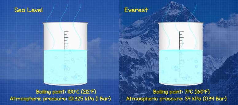
So what is cavitation? As we know, water can turn from a liquid state into steam or a gas state. The point at which this occurs is known as the vapour pressure.
We know that water boils at around 100°C (212°F) and that’s because it’s at sea level which has an atmospheric pressure of 101.325 kPa (1 Bar) but if we went to the top of Everest then water boils at just 71 °C (160 °F) because the atmospheric pressure has reduced to 34 kPa (0.34 Bar). As pressure reduces it becomes easier for water to boil.
So at the suction inlet of the pump we know that there is going to be a pressure drop and if this pressure is less than the vapour pressure of the liquid being pumped then the water can reach boiling point. When that happens cavitation occurs.
During cavitation air particles within the water will expand as they reach boiling point, these will then collapse in on themselves very rapidly. As they collapse they can damage the impeller as well as the pump casing, this removes small parts of metal from the surface and if this keeps occurring then it will eventually destroy the pump. Therefore we must ensure the available pressure is higher than the required pressure of the pump.

Where Do We Use Centrifugal Pumps?
We use centrifugal pumps everywhere. We use them to move liquids from one tank to another or around a system.
For example we might use a small inline centrifugal pump in our domestic heating circuit to move heated water around the property.

We might use large centrifugal pumps to move the condenser water from a chillers condenser and up to the cooling tower on the roof as part of the centralised cooling system.
We’re going to look at the types of pumps and their applications in our next article in this series.


")


")

")

[…] If you want to know how a centrifugal pump works then we have covered this in detail in our previous article. CLICK HERE. […]
Thank you for sharing the mechanism of the centrifugal pump. The other day my contractor was mentioning that my pipeline needs to include a centrifugal pump as I have water sources coming from more than one source. It is interesting how it helps control the water flow and able to control the source, I will definitely give the go-ahead to my contractor.
I thoroughly enjoyed this article. So educative. Thank you.