

Learn how PICV’s work, why they are used, where they are used and how important they are, along with worked examples.
Scroll to the bottom to watch the YouTube tutorial.
Check out Danfoss PICVs and matching 3D BIM library for modern MEP HVAC designs: CLICK HERE
Danfoss is engineering HVAC 4.0 for smart buildings:
With its dynamic hydronic balancing and high-accuracy control performance in partial load conditions, Danfoss PICVs improve indoor comfort in public and commercial buildings. At the same time, they increase the energy-efficiency of HVAC systems, so they perform with the lowest possible operational costs.
Equipped with NovoCon series digital actuators, detailed HVAC system data is made available for Active Energy Management (AEM) by BACnet or Modbus connected Building Management Systems (BMS).
Learn more about the full range of Danfoss PICVs and Actuators: CLICK HERE
What is a PICV?
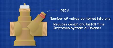
Pressure independent control valves will often be abbreviated to the letters PICV. This is a type of valve found in Hydronic systems, meaning water based, which provide heating and cooling in buildings. These valves are basically a number of different valves conveniently combined into one unit. This saves on design and installation time as well as improving the efficiency of the system. They have two main functions which are to control the amount of liquid flowing through a pipe and to automatically adjust and compensate for pressure fluctuations in the system to maintain a stable and reliable control.
What Do PICV Look Like?
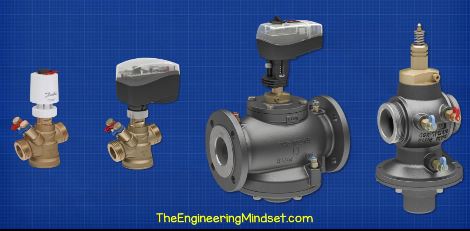
There are many variations of this valve. As you can see, their design changes as the size of the valve increases but their operating principle is almost the same.Let’s look at a smaller version to understand how it works.
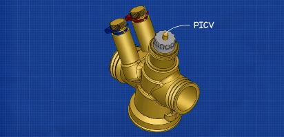
So the valve will look something like this.
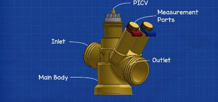
We have the main valve body and we have the inlet and outlet attached to this. This is where the fluid we’re controlling will flow into and out of. There’s an arrow on the side to indicate the direction of flow. Then we have two ports with coloured tabs. Not all models will have these, but these ports allow us to connect a measurement device to take manual pressure readings to verify the valves operation. The colours correspond to the high pressure side which is red and the low pressure side which is blue.
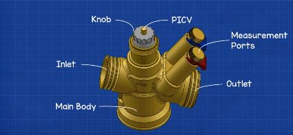
On the top we have a knob which can be rotated, this can be used to adjust and set the flow rate through the valve and there is a number scale on the knob to help configure this. There’s also a thread on the top which allows us to attach an actuator for remote temperature control via a building management system.
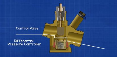
Inside the valve we have two main sections. The top section, on this model, is the control valve which controls the flow rate of water through the valve.. The bottom section is the differential pressure controller. The differential pressure controller automatically detects and adjusts its position when the pressure of the incoming fluid changes. However, the control valve must be manually adjusted either by hand or through an actuator for remote operation. We’ll look in more detail how these parts work a little later in this video.
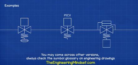
When we look at engineering drawings we will see the valve represented by symbols like these, there are other variations so always check the symbol information section.
Where Do We Use PICV?
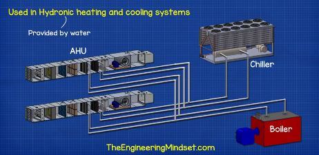
So where do we use PICV’s? Well as briefly mentioned earlier, we use PICV’s in hydronic heating and cooling systems. These are found for example in offices, hotels, hospitals, schools etc.

There are many applications for these in both heating and cooling system, but some of the most common ones are as follows:

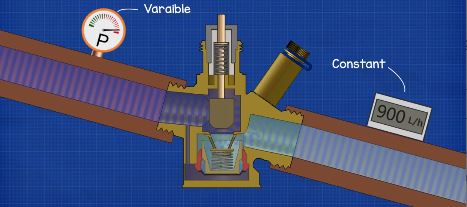
Variable flow systems, where we have a variable speed pump on the secondary side and this is supplying an air handling unit, maybe some chilled beams and maybe also some fan coil units. We’ll see them used with room controllers and actuators to provide temperature control to each unit.
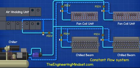
Constant flow systems, where the main pump doesn’t vary it’s speed, we will usually find 3 port control valves used to bypass the units and we can also use PICV’s here as flow limiters. This allows us to automatically balance the system and avoids overflow in part load operation.
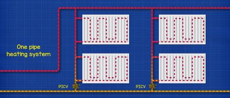
We also find them used in one pipe constant flow radiator systems.
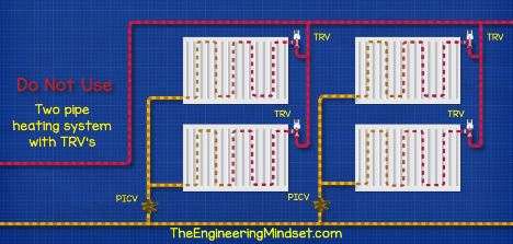
Somewhere we can’t use them is on 2 pipe heating systems with TRV’s installed on the radiators and with the PICV used as a flow limiter in the riser. This is because the valve will maintain a constant flow in the riser so it will work against the TRV’s.
Why Do We Use PICV?
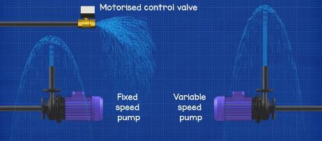
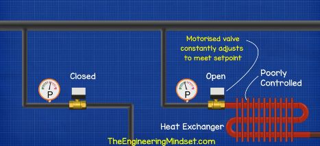
In a hydronic heating or cooling system, we have pumps which boost the pressure and circulate the water. As we saw, some systems have pumps which vary their speed to change the flow rate and thus system pressure. We also have control valves which open and close to control where and how much water is flowing through the heat exchangers.
The problem we face is that as valves open and close, as well as when pumps increase or decrease their speed, the pressure in the system changes. Why is that a problem? Because the control valves are trying to restrict how much water is flowing through them, as the supply pressure increases and decreases the flow rate through them is going to increase and decrease also. This means we do not have control of the valves operation or how much heating or cooling is being provided. When the valve is connected to an actuator for temperature control, the valve will have to constantly adjust itself to try and maintain the flow rate. This is going to eventually cause the valve or actuator to fail because it’s constantly moving. To control the valve and flow rate we need a way to control the pressure difference across the valve regardless of changes in system pressure.
To visualise what we mean by this, we want you to imagine a vessel.
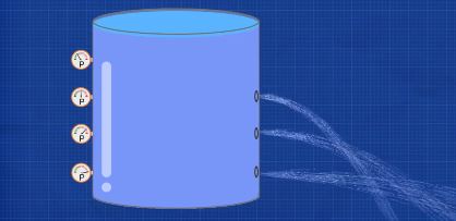
If we fill the vessel with water, the pressure in the vessel is going to increase the deeper we go because of all the force above it pushing down. If we made some holes, of the same diameter, into the vessel at various depths, then the pressure is going to force the water out. The deeper the hole, the higher the pressure. The higher the pressure, the higher the flow rate and velocity of the water leaving the vessel. As the water level decreases, the pressure decreases and the velocity decreases.
For the next point let’s consider a vessel with a single hole. As we saw earlier, the water level decreases as it’s exiting and flowing through the hole. As the water level decreases so does the pressure and the flow rate through the hole. What’s happening here is there is a pressure difference between the inside and outside of the hole and this pressure difference changes the flow rate.
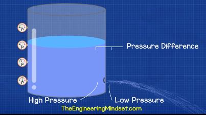
To ensure the flow rate out of the hole remains constant, we need to balance the pressure difference. We can simply do that by topping up the water level and replacing the same amount that is leaving, That way the pressure difference remains the same across the hole.

Now that the pressure difference is stabilised and the flow rate is constant, we can then control how much water can flow out of the vessel by simply creating a restriction to the hole. This acts to decrease the size of the hole so we can reduce the flow rate.
So that’s a rough concept of how the pressure independent control valve works.In this example we simply add more water into the vessel to regulate the pressure, but in the actual valve we will use some special mechanisms to achieve that instead, and we’ll see that shortly.
So what this means for our heating and cooling systems is that the flow rate can be controlled and maintained despite other pumps and valves varying their position.That way the system is balanced and the heat output is controlled through the heat exchanger.
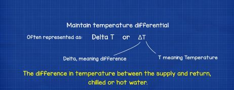
Another benefit to this is maintaining the delta T or temperature difference within our heating and cooling system. That’s the difference in temperature between the supply and return chilled or hot water. Take a typical cooling coil which is providing cooling to the air passing over it. The coil is supplied chilled water from a central plant chiller at around 6°C (42.8℉). After this has provided cooling to the air, the chilled water will ideally leave the coil at around 12℃ (53.6℉). That gives us a delta T of 6 degrees (10.8℉) which is ideal. The chiller will operate very efficiently at this level.
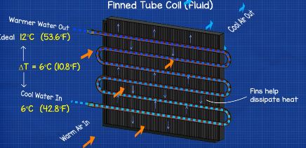
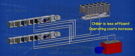
But when we can’t control the flow rate in the system and therefore the delta T on the coils, then the system can develop low delta T syndrome. The chilled water might exit the coil at 9℃ (48.2℉) giving us a temperature difference of just 3℃ (5.4℉) that’s going to dramatically affect the chillers efficiency and also cost more to run. So we want the delta T to be as large as possible.
By maintaining the pressure difference we can use the control valve to ensure the flow rate is exactly what we need to achieve that high delta T.
How Do They Work?
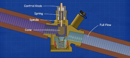
First let’s look at the control valve. The control valve acts like a normal valve. It has a cone which moves up and down to decrease or increase the area available for a fluid to pass through. This is attached to the spindle and the control knob. When we turn the control knob by hand or use an actuator to manoeuvre it remotely, it will force the shaft up or down to open or close the valve. As the valve closes, the amount of fluid flowing decreases. As the valve opens, the volume flow rate increases. So as long as we can maintain the same pressure difference across the valve, we can accurately tell how much water will flow through the valve at a given position. We can lock the maximum flow rate through the valve to balance the system.
Now let’s look at the differential pressure controller.
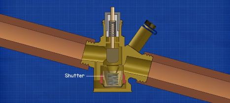
This model of valve uses a small cup, known as a shutter, which rises and falls to compensate for fluctuations in pressure within the system.
The shutter sits concentrically within a guide to ensure it slides up and down correctly. A downward force acts on the shutter by use of an internal spring, the spring is held in place by a support frame. Underneath the shutter is a flexible membrane which acts as a physical barrier between the high pressure inlet and the lower pressure outlet.. A small passage connects the cavity on the underside of the membrane to the inlet. This way when water flows through the valve, some of it will flow into this small hole and the pressure of the incoming fluid will force the membrane to move upwards. That pushes the shutter up to maintain the pressure difference across the valve.
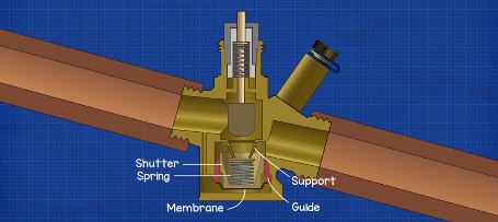
The spring helps to maintain the correct force and pressure difference between the two sides of the valve. Between the pressure difference of the fluid and the force of the spring, the valve reaches equilibrium, and it does this constantly and instantly as the system pressure changes. This allows the flow rate to be maintained regardless of pressure.
The control valve can control the quantity of water flowing through the unit and the pipes. This can be done manually or via an actuator. Meanwhile the pressure controller will autonomously modulate it’s position when it detects a fluctuation in the system pressure. By combining these two functions, this allows the valve to operate in a linear fashion regardless of the pressure in the system. Therefore we have our pressure independent control valve.


")

")
Finding this website super amazing
good morning sir, if we select flow of PICV big than our requirement. what is problem?