

Learn how the alternator works. This device is an essential part of every combustion engine vehicle’s electrical system. So, what does it do and how does it work. In this article we will be looking at the typical car alternator to understand how it works, the main parts as well as why and where we use them.
Scroll to the bottom to watch the YouTube tutorial.
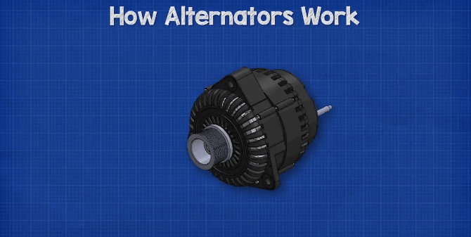
What is an Alternator
An alternator looks something like this. We find the alternator within the engine bay of the car.
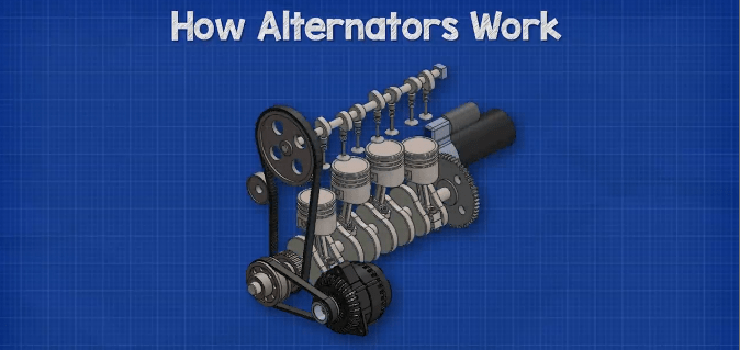
The shaft of the alternator is connected to the engine via a belt and pulley. When the engine is running, the shaft of the alternator is forced to rotate, this rotation generates electricity.
The alternator produces a type of electricity known as AC or alternating current, which is why it’s called an alternator. With AC electricity, the current of electrons flows forwards and backwards constantly. This is the same type of electricity you will find in your power outlets within your homes, but the voltage in your homes in much higher.
However, all the electrical components within the car use another type of electricity known as DC or direct current. With this type of electricity, the electrons flow in just one direction, this is the same as the electricity you get from a battery.
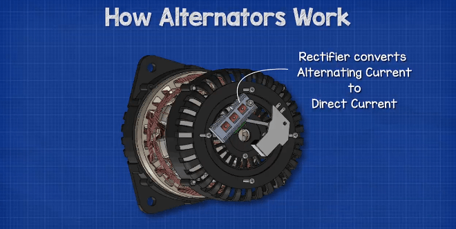
So the alternator converts the Alternating current into direct current via a rectifier. The output voltage of the alternator varies with the speed of the car, so the alternator also uses a regulator to limit this and maintain a near constant output.
Why is an Alternator Used
Every modern vehicle needs electricity to operate, this is used to power things such as the lights, music system, electric windows, window wipers etc.
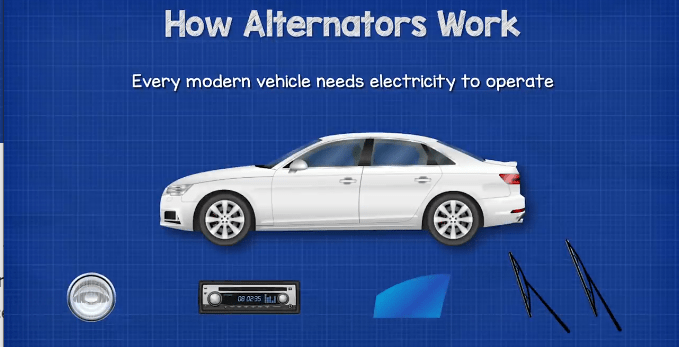
The engine combusts fuel. This is used to turn the crankshaft and propel the vehicle along. The engine only provides mechanical force, it does not produce electricity. So, we need a way to power all the electrical devices within the vehicle and that’s where the alternator comes in.
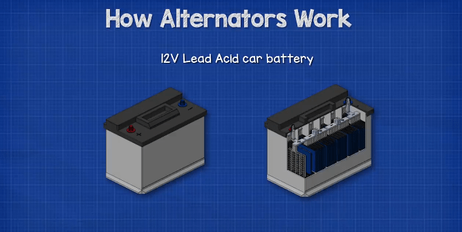
In the engine bay we also find a 12V lead acid car battery. This stores energy in the form of chemical energy, it does not store electricity.
By the way we have covered how the car battery works in great detail, check that out HERE
When the engine is off, the battery powers the cars electrical components. This will drain the battery though.
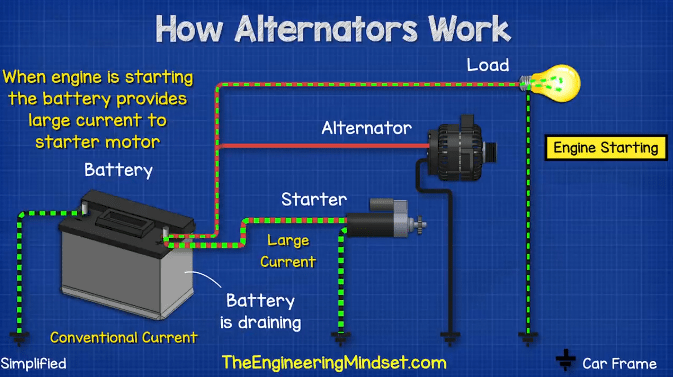
When the car starts, the battery provides a huge amount of current to the starter motor which turns the flywheel and starts the engine. The battery is again partly drained during the start up because of the large current required to turn the starter motor.
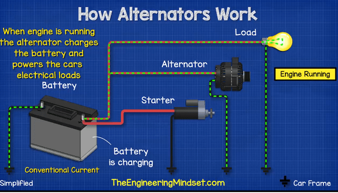
Once the engine is running, the alternator is used to recharge the battery so that it has enough stored energy to start the engine again in future. The alternator will also power the cars electrical devices while the engine is running.
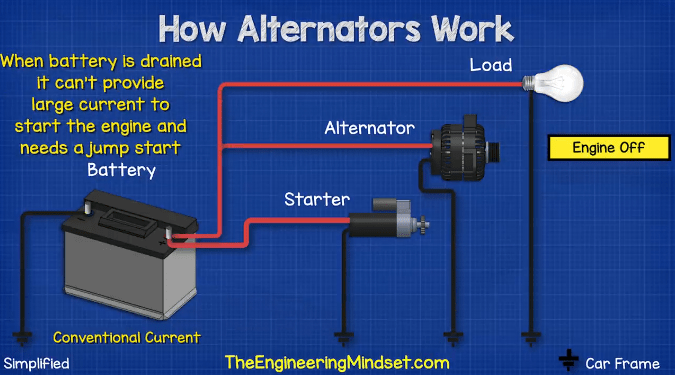
If the battery is left to discharge for too long, it will not be able to provide the large current necessary to start the starter motor and the car will need to be jump started.
The Main Parts
Let’s have a look at the main parts of the alternator. At the front of the unit we find the pulley. This is a wheel which has grooves cut into it that help grip the belt that provides the rotational force from the engine.
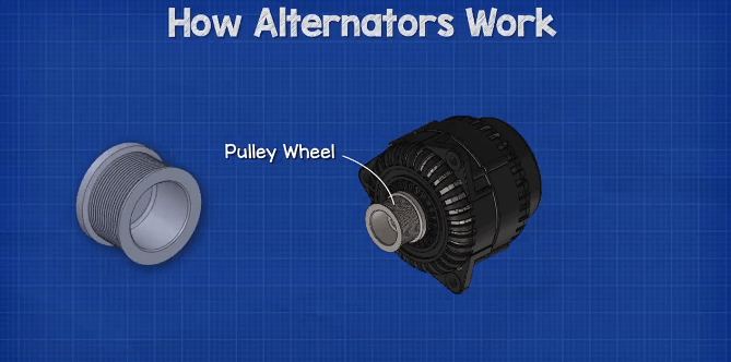
The pulley wheel is attached to the shaft which runs through the entire length of the alternator.
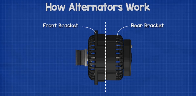
The internal components are held inside the main housing. The housing consists of 2 parts, the front and rear bracket. There are some slots cut into the casing to allow air to pass through and remove the unwanted heat which is generated.
At the back of the unit we have the electrical connections. There are many different designs but this is an example of a simple 3 wire design, with an internal regulator and rectifier which has the following terminals:
B terminal. This is the output which charges the battery.
S terminal. This allows the regulator to sense the voltage.
F terminal. This is connected to the ignition and provides the initial power to the electromagnet at start up.
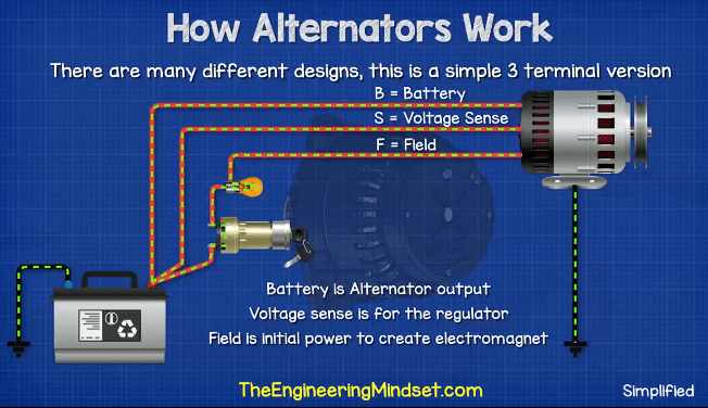
To complete the circuit, the electricity flows back through the cars frame to or from the battery’s negative terminal.
As this unit has an internal regulator and rectifier, we find these components at the rear of the unit, usually under a protective cover. We’ll see those in more detail shortly.
By removing the housing we can see inside the unit. The first thing we see is the stator. The stator is stationary and does not rotate.
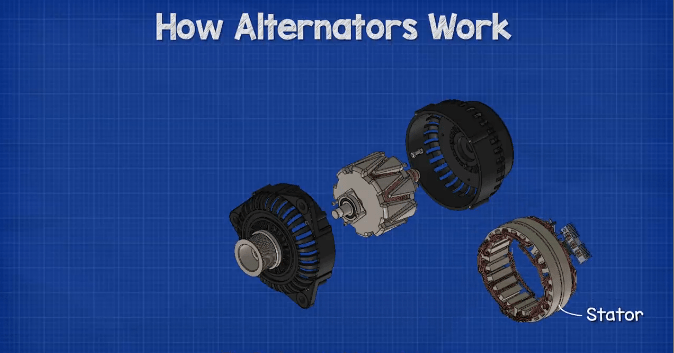
This consists of a number of laminated sheets which have a pattern of slots around the inner edge.
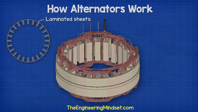
Then we find 3 separate sets of copper wires which are wound between these slots in a certain order. One end of each coil is connected together to form a neutral point, this is a star configuration.
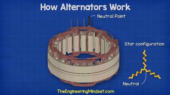
Each coil set will produce a single phase of AC electricity, providing 3 phases in total. The other end of each coil passes through the case and attaches to the rectifier.
The alternator produces AC alternating current but the battery and electrical devices of the car need DC. So the rectifier is going to convert the AC into DC electricity.
At the centre of the alternator we find another coil of wire which is wound around an iron core and is connected to the shaft. The shaft also holds two slip rings. The slip rings are connected to opposite ends of the coil. Within the rear housing we find some brushes. These are some spring loaded carbon blocks which are pushed outward to rub against the slip rings to form an electrical connection. The car battery initially provides electricity to the coil via the brushes. As the electricity passes through the coil, it generates an electromagnetic field.
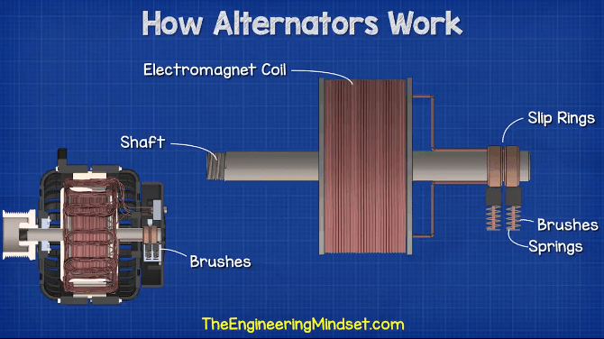
To enhance this electromagnetic field, two iron claws are placed either end of the coil which interlock with each other. One end will become the north pole, the other will become the south pole.
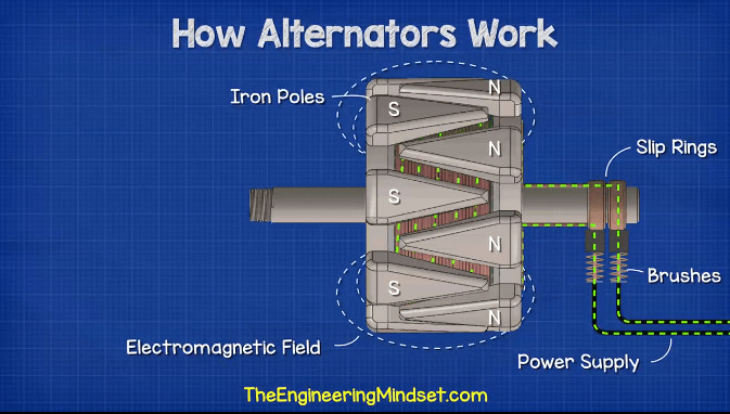
As the electromagnet is attached to the rotor shaft. When the engine turns the shaft, it also rotates the electromagnet past the coils of the stator. This will cause the stator coils to generate a current, and so electricity is generated.
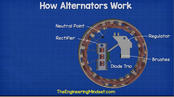
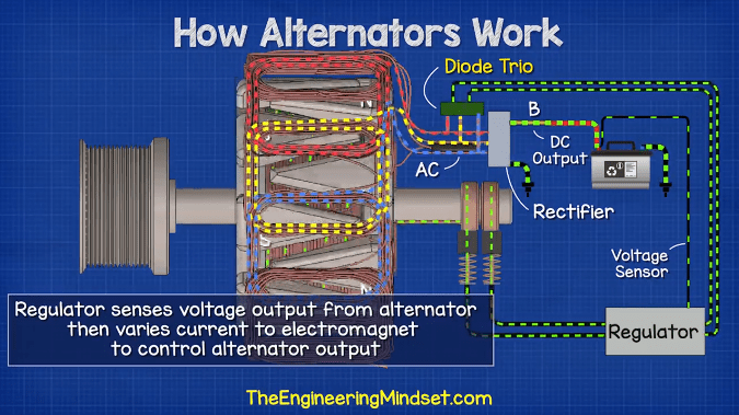
Once the alternator is generating electricity, the alternator is able to power the electromagnet by itself via a diode trio which converts the 3 phase AC electricity into DC.
The voltage and current produced by the alternator will vary with the speed of the vechical, the faster the vehicle travels the faster the crank shaft rotates and thus the faster the alternator rotates which increases the voltage and current. To control this, another component is used called the regulator which is mounted at the rear of the unit.
This is an integrated circuit board which monitors the output of the alternator and varies the current flowing through the electromagnet to control its strength. The strength of the electromagnet can be used to vary the output of the alternator.
How Electricity is Generated Within the Alternator
Electricity is the flow of electrons in a wire. The copper wire is made from millions and millions of copper atoms. Each atom has a free electron. This is an electron which is able to move freely between other atoms. It does move to other atoms by itself but this occurs randomly in any and all directions which is of no use to us.
We need lots of electrons to flow in the same direction and we do that by applying a voltage difference across the two ends of the wire. This forces the electrons to flow. If we reverse the battery, the electrons flow in the opposite direction.
When electricity passes through a wire, an electromagnetic field is generated around the wire. If we place some compasses around the wire and pass a current through it, the compasses align with the magnetic field. If we reverse the direction of current, the magnetic field reverses and the compasses change direction.
If the wire is wrapped into a coil, the magnetic field becomes stronger. Each cross section of wire still produces an electromagnetic field, but they combine together to form a larger, stronger, magnetic field. The electromagnet generates a north and south pole, just like a permanent magnet, and we can see that by again using some compasses. If we increase the current to the coil, the electromagnetic field increases.
We can also do the opposite. If we pass a magnet through a coil of wire, a current is generated in the coil. The dial on the ammeter indicates a current flowing in a forward direction, this is therefore generating a DC or direct current. When the magnet stops moving, the dial returns to zero. When the magnet is moved in the opposite direction, the current flows the opposite way and the dial indicates a reverse current.
If we move the magnet in and out repeatedly, the current will therefore alternate between flowing forwards and backwards. This is how AC or alternating current in generated. The current is alternating in direction.
If we move the magnet faster, a stronger current is generated.
If we use a stronger magnet, then the current also increases.
If we use a larger coil with more turns, then this will also generate a larger current.
Instead of using a permanent magnet, we could use an electromagnet. As we move this in and out, it will also generate an AC current in the coil. But with the electromagnet we can adjust the current and voltage to vary the strength of the magnetic field, this lets us control how much current is generated in the coil.
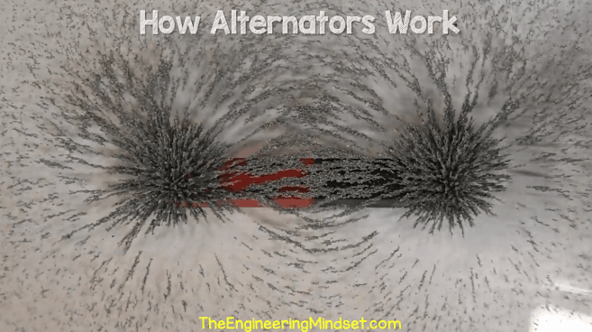
Instead of moving a magnet in and out of a coil, we can generate a current much easier by rotating the magnet and placing the coils around this. The strongest part of the magnetic field is at the ends where the magnetic field lines converge. You can see the magnetic field lines by sprinkling iron filings over the magnet.
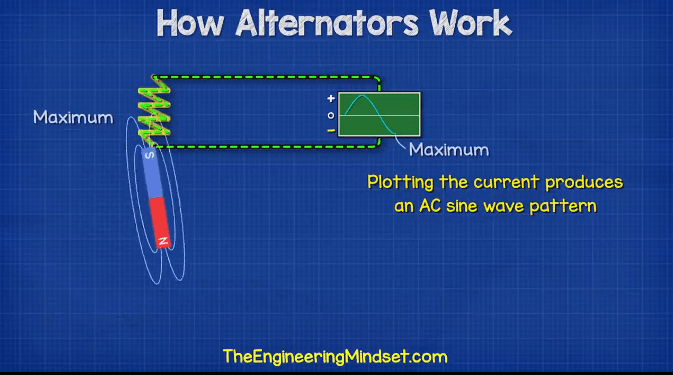
With the magnet between the two coils, there is no current generated, but as the magnet starts to rotate, the strongest part of the magnetic field gets closer and closer to the coil. The coil experiences a changing intensity of the magnetic field, this will cause more and more electrons to be pushed forwards up until it’s maximum intensity. Then the magnet starts to move away from the coil, so the magnetic field begins to decrease and so does the current of electrons until it reaches zero again. Now the opposite end of the magnet begins to get closer to the coil and this pulls the electrons in the opposite direction, again to a maximum point and then decreases back to zero. So, if we plot this current on a chart, we get a sine wave with the current flowing in the positive and then negative regions. This setup gives us a single phase, AC supply.
But, we have all this empty space between the coils, which seems a bit of a waste. So, what can we do with this space? Well, we can add more coils and create more phases to provide even more power.
If we place another coil 120 degrees rotation from the first phase, this will give us a second phase. Why? Because the coil is at a different angle, so it will experience the change in intensity of the magnetic field at a different time. The current is therefore going to flow forwards and backwards at a different time. That gives us another sine wave, which occurs at a different time.

We still have empty space here, so we can add another set of coils at 120 degrees from the previous to create a third phase.
If we used just a single phase, then for every rotation of the magnet, half the time the current is flowing forwards and half the time the current is flowing backwards. But with three phases, we always have a phase which is flowing forwards and always have one which is flowing backwards. Which means we can utilise this to provide more power.

Instead of having 3 separate coils and 6 wires, as the phases are always switching between forwards and backwards, we can connect the ends of the coils together. The current will then flow freely between each coil as it changes direction.
Now, we are producing 3 phase AC electricity. But, all our electrical circuits and components within the car use DC or direct current. So, we need to convert AC to DC, and for that we use a full bridge rectifier.
This is essentially just 6 diodes connected in pairs and wired in parallel. If you don’t know, diodes only allow current to flow in one direction and block the current in the reverse direction. So, with a single phase supply, for every turn of the magnet, current will only flow for half of the turn, the other half will be completely blocked.

If we connected each of the 3 phases separately to a diode, then the current will flow or be blocked at different times. Therefore, we can combine the phases into a block of diodes, and only the phase nearest its maximum will be allowed to pass through. Giving us a slightly rough DC output. To smooth this out we can connect a capacitor which will basically absorb electrons and then eject electrons automatically to maintain a constant output. This gives us a constant DC supply.
By the way we have covered diodes, capacitors and power inverters in great detail previously. Do check those out here- DIODES, CAPACITORS, POWER INVERTERS.
OK, so we now have a DC output. But, if the magnet is connected to the engine, and the car speeds up, then the magnet will spin faster and that will increase the output voltage and current. We don’t want that because it will kill all of our electronic components within the car. So, we need a way of regulating the voltage.
If you remember, we saw that by using an electromagnet, we can increase or decrease the electromagnetic field strength by varying the voltage. And by varying the strength of the magnet we can vary the voltage and current generated in the coil.
That’s why the alternator uses an electromagnet so that it can control the output. The car battery powers the electromagnet. Although most modern alternators will use a diode trio which converts the Alternating current of the alternator into direct current and powers the electromagnet via a voltage regulator once the alternator is generating electricity.
On the power supply of the electromagnet, within the regulator, we find a component known as a transistor. The voltage sensor is also connected to the regulator.

The transistor is a type of electronic switch which can be turned on and off thousands of times per second by a controller. This can be used to control the amount of current flowing.
If we imagine the current flowing through the coil, from the battery, is at its maximum level for a given period of time, then we get 100% current and the electromagnet is at 100% strength. But, if we now use the switch so that the electricity only flows for half the time, then we get 50% of the current and therefore the electromagnet is only 50% of its strength.
So by measuring the output of the alternator and then varying the open and close times of the transistor switch, we can control the current flow through the coil and the strength of the electromagnet. This controls how much electricity is being generated by the alternator to maintain a constant output.
But now that you’re all charged up, checkout squarespace.com to create your own online web presence which is packed with features to empower individuals to launch, share and promote their own projects.
There’s powerful blogging tools to showcase your projects photos, videos and progress updates.
You can easily schedule appointments for classes and sessions with team members and clients through their built in tool. And you can even collect payments or donations to help support your cause.
Head to squarespace.com for a free trial, and when you’re ready to launch, go to squarespace.com/engineeringmindset to save 10% off your first purchase of a website or a domain.


")

")

[…] The alternator is the component that charges the battery. So, if it breaks or malfunctions, there’s a good chance […]
I really enjoy studying with you. I have learn a lot from you. Please continue sharing ideas with us. Thanks so much.
recently the alternator of our diesel went bad. when we went to get it fixed, the technician said that some of the diodes have burnt up and we needed to replace the entire rectifier bridge. Our bridge had 4 diodes(or 4 pairs?) and we were only able to find 3 diode(3pairs?) bridges in autoparts shops. the technician said that the “3 diode” bridge works fine, but wouldn’t produce as big a current as the “4 diode” bridge, so it might be insufficient for our requirement.
can you please teach me how the 4(or 8) diode arrangement works? and why it produces a larger current than the 3(6) diode arrangement?
PS-our technician said 3 diode system and 4 diode system…but after going through your article i assumed that he might’ve called the arrangement with the 3 pairs of diodes as the 3 diode system, and that we needed a bridge with 4 pairs of diodes
PPS-both 3 diode and 4 diode rectifiers were available for our alternator model, and both worked fine. so i don’t think that there is a difference in how the coil in the alternator is wound up. The only difference was that the 3d bridge couldn’t charge up our battery as fast as the 4d bridge did
Just to make it really clear for you madam/sir, that if the technician changes the connection on your stator, lets say the rectifier you brought is compatible to the Icy voltage regulator you have, lets just put it that way um so this what happens now is that it is really up to the transistor from the voltage regulator if it can still produce the same amount of voltage from what has now the stators has giving unto it. So let says they are compatible both your new rectifier and old regulator. This means now that it is up to the job of the regulator if it can still produce the same amount of voltage that the electronic devices your car or truck needs. Hope this adds answers your question madam/sir.
PS: Maybe soon also TheEngineeringMindset will come to the time that he will explain to you 24V alternators that has 2sets of rectifiers so that ppl can also learn on 24V powered vehicles because for me this is you know the thing that you love to do and work, like this makes you happy so I am also happy that ppl will have a little knowledge about this so that they can easily handle and identify what is the problem on their cars because a lot they mistakenly just put the answer of the problem unto the battery, of course we know its the battery if your car doesn’t start but we need to put our minds a little wider and put what ifs in it, like what if my alternator is not charging thats why my battery cannot start up my car, something like that right? cause commonly ppl will end up buying new battery’s and I am not discouraging them not to buy new ones cause time goes by you really need to change the battery but just to lessen the expenses if your just living life same like me that the profit just good for us to survive the day, just to lessen and help others out please think wider so that the problem doesn’t put you to the place you don’t want your self to be. But lets says your bill gates son or maybe his daughter you can just throw away your car and buy a new one lmao. But that just an example. Hope this helps 🙂
hello madam/sir, I’m a guy who fixes alternator and starter motors here in the PH and I have experience a lot with fixing alternators and starters here even improvising those and just to tell you, I mean just to add up some information as what I have experience with fixing the alternators here, So you were saying that you can only find a 3 positive negative set rectifier, so just to give some info um just to be direct on what you are questioning them. The rectifiers set of diodes always depend on how many set of alternator phase did the company of the alternator put in the stator, to make it simple it depends on how many set of coils are there in the stator. I hope that answers your question.
2nd is madam/sir, as what your technician says that its okay to put the 3 diode rectifier, I would say that It really depends on how he will fix your alternator so um let me put it this way to make it easy, lets say you bought the 3 way diode, so this what happens and this is base on my experience only madam/sir and to all ppl if someone will read this, you can correct me if I’m wrong cause I’m not that perfect, the solution that he agrees on that is he will change the connection on the stator and by doing that he will just make us of the 3 phase AC from the stator and still your 3 bridge rectifier will still produce DC current, but here also a question also that you wanted to have an answer. This part I’m really not a hundred percent sure but based as what I have learned here in TheEngineeringMindset, as what I have saw on the video so this will come to the regulator cause he is the one responsible for how much is DC is going on the battery and specially to the main component on the regulator which is the transistor, so to conclude this it depends on the transistor if it can still be able to produce same amount of voltage coming out from the alternator unto the battery that means also that as what I have experience here on my daily basis work here in PH since the very start. In my knowledge I experience also that some rectifier is really isn’t compatible with the regulators.
PS. Just to add up some small info, some rectifier also has no capacitors on the rectifier because the regulator or Icy voltage regulators what they call it now, has already the capacitor attach on it, and also sometimes both the icy voltage regulators and the rectifiers do have capacitors attach on it. And that’s all I can share on my knowledge base for as what I have learned and experience through the years here in my country or in my place to be specific on fixing them. I hope this not to conclude that I have answer what you are questioning base on the video because I know I still have a lot to learned and to know what more do the companies are planning to design them alternators just to improve its performance but I hope this gives you a little knowledge about alternators <3
It’s just great! Thank you!