Scroll to the bottom to watch the YouTube tutorial.
Sponsored by PCBWAY.

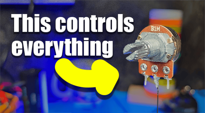
This is a potentiometer. It’s an adjustable resistor. They come in many shapes and sizes.

We can insert them into test boards, connect wires to them, solder directly to them or solder them onto circuit boards.
They usually have a dial, a slider, or an adjustable screw head, which lets us change the resistance of the component.
They are represented with symbols like these in engineering drawings.

We can use them to manually adjust the voltage or current in a circuit. When used to adjust current, we call it a rheostat. I’ll explain how to use both of these later in the article.
See this game controller, well the joystick has two potentiometers. One measures the up and down movements, the other measures the left and right movements.

This is a servo motor, used in robotics. Inside we also find a potentiometer, which is used to check and control the position of the arm.

This radio uses a potentiometer to control the volume.

This DC power supply uses a potentiometer to control the supply voltage.

This audio equipment uses a slide potentiometer.
So where have you seen them used, let me know in the comments section down below.
OK so how do they work?
If we look at a typical rotary potentiometer, we notice there is a metal protective casing on the back which is simply held in position by these small arms on the front.
All the parts connect onto a small brown sheet of insulation. Along the top edge we usually find some letters and numbers. I’ll explain these in just a moment.
We then notice a long shaft rising up off the device. We can rotate this to alter the resistance of the component. You’ll see there is a slot cut into the top for a screwdriver, or on the sides are some ridges which just help us grip the shaft. We can also attach a knob onto this.
At the base of the shaft there is a threaded section, we can use this to attach the component to a sheet of material.
Along the lower edge are three metal terminals. We connect our circuit to these terminals. These terminals can be straight or angled depending on the application.
When we remove the back case, we can see there is a track which runs between the two end terminals. Another track runs in a loop at the centre and connects only to the centre terminal. The outer track has a very dark material over it, this is the resistive material.

This track even looks like the symbol for resistance, so it’s very easy to remember.
A wiper forms a bridge between the outer and inner track. It is slightly spring loaded to ensure a good connection. This is attached to the shaft. Rotating the shaft rotates the wiper. The further we rotate the wiper, the further the electrons will have to flow to get to the centre pin. So, the resistance increases.
We can also reverse the connections so that we reduce the resistance as the shaft rotates.
On the printed text, we usually find a k or M at the end, meaning thousand or million.
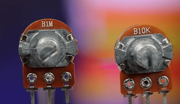
This one shows 1K meaning it’s 1,000 ohms. This one shows 500k which is 500,000 ohms. This one shows 1M which is 1 million ohms. These values tell us the maximum resistance of the component.
The first letter indicates the type. B is very common, it means the resistance changes in a linear pattern. Then we have type A, which gives us a logarithmic pattern, we also have type C which gives us an inverse or reverse logarithmic pattern. However, the letters used can vary by country and also manufacturer so always check the manufacturers datasheet or check the performance with a multimeter.
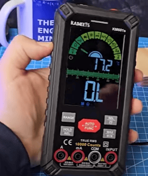
By the way, this is the new smart multimeter from kaiweets, our viewers can get an exclusive 15% discount off all their tools by using code EM15 at checkout. Check it out HERE.
By using the resistance function on our multimeter, we can see this 1 thousand ohm potentiometer has approximately 1,000 ohms of resistance across the entire resistive track. We can connect between terminal 1 and 3 to measure that. Or, we can measure this directly across the internal resistive material.
Notice the resistance reduces as we move the probe. We can plot this and we notice that at about half way we have half the total resistance. This is therefore a linear B type potentiometer.

This one also has 1,000 ohms across the end terminals but notice the resistance changes logarithmically along the entire track. This one is also 1,000 ohms but it changes reverse logarithmically along the entire track. Logarithmic is often used for volume control as it matches the human ear. Linear is used for things like lights and motor speed control.
I’ve used the linear version here to control the colours of this RGB LED. I explain how it works later in the video but you can download my PCB project files for free using the link in the video description, you can then order the circuit board from PCBWAY, our sponsor. You just need to upload the file to their website, it will automatically fill in the options for you, but you can make changes such as the board colour if you wish, then just place your order and soon your PCB’s arrive in the post. They look fantastic. We just solder the components together and we have made a simple RGB controller. Use my link to get $5 off your first order from PCBWAY. They do also have an amazing shared projects library full of user generated inventions. PCBWAY also offer pcb assembly, CNC machining, 3D printing and even sheet metal fabrication so you can design and build anything. Do check them out HERE.
We can get these dual versions, which are basically just two potentiometers joined together. Both are controlled from the same shaft. Useful in 2 channel stereo audio volume control.
Be careful though, these have a low power rating (0.2Watt) and can easily be destroyed. These can typically be adjusted 10,000 times or more. They don’t fully rotate, usually just around 270 degrees.
You can buy them individually or in assorted kits depending on your needs.
There are multi-turn potentiometers. They also come in different sizes and usually have a threaded section for mounting. They have a long shaft which the control knob fits onto.
This is a 10 turn version, meaning the shaft can rotate 10 times. This gives us very precise control of resistance. It can usually handle slightly more power too. This one can handle at least 1 million adjustments.
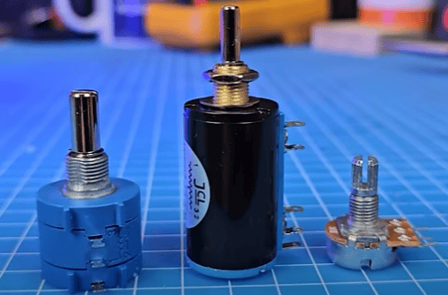
Notice that the body is much longer than a regular rotary potentiometer, that’s because inside is a spiral wire track which provides a fixed resistance. This connects to the top and middle terminals. At the centre, connected to the shaft, is a slider which can freely move up and down along a conductive track. This is electrically insulated from the shaft. The conductive track connects to a circular terminal at the base, allowing the shaft to rotate. The flexible connector ensures a firm connection. The slider rotates with the shaft. The plastic slider has some ridges which fit over the resistive coil, when the shaft rotates, the ridges will therefore follow the curve of the wire., so it moves up and down as the shaft rotates. A small spring arm sticks out of the slider and rubs against the wire coil. This also rubs against the conductive track, providing a path for the electrons and allows us to use just part of the total resistance.
This one has a wiring diagram on the case, showing the fixed resistance is between the centre and right pin. The wiper is connected to the left pin.
On the back it shows a maximum resistance of 5 thousand ohms.
Slide potentiometers look something like this. We slide the dial to adjust the resistance. They often have a flexible cover for dust protection.
Inside we have a resistive track and a conductive track. The wiper acts like a bridge between the two tracks, moving the dial moves the bridge and changes the resistance. The 3 pins are sometimes numbered underneath, but not always. We also have 6 pin versions which have two sets of tracks inside. These are basically just two slide potentiometers joined together.
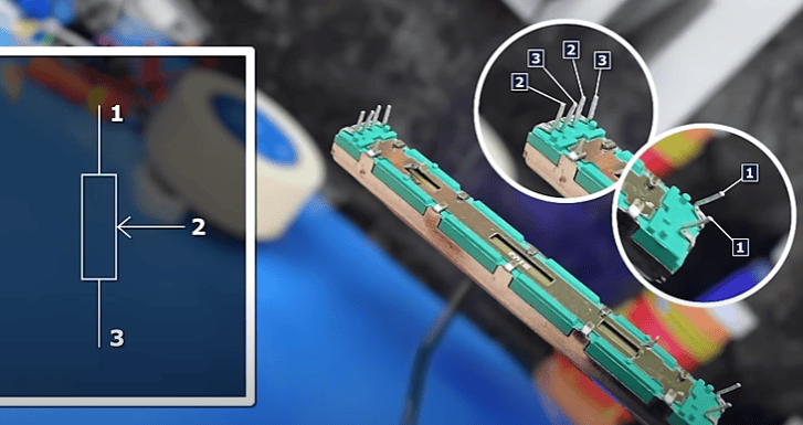
There are usually some other pins which are just for mounting the device. You can check the datasheet for pinout diagrams or just use a multimeter.
Printed on the bottom are some letters and numbers. The first letter tells use the type of taper. The numbers tell us the maximum resistance. This one shows 103, meaning 10 with 3 zeros after, which is 10,000 ohms. This one shows 100K which means 100,000 ohms.
They do usually have low power ratings and are typically rated for at least 10,000 adjustments.
Trimmer potentiometers look something like this, and use these symbols. These are much smaller and only designed for calibration of circuits with very occasional adjustments.
At the centre is a rotating part with a small screw slot or maybe a knob with an arrow. These versions have less than one full rotation of movement so they aren’t as precise and the multi turn versions, I’ll explain these also in just a moment.
They do have a low power rating so be careful. They will break easily, and are only designed for occasional adjustments.
Inside we have a resistive track running between the two end terminals. A circular conductive plate connects to the centre terminal. A tiny wiper bridges across the two tracks and is held in place by the rotor.

With this exposed version we can see the resistive track running between the two end terminals and then the wiper arm connects to this and rubs along it as we rotate it. It then connects down through the centre pin, onto the middle terminal.
Sometimes they have a small wiring diagram printed on them. But the unaligned pin is generally the wiper pin. It’s easy to test with a multimeter.
These small versions have a 3 digit number printed onto them, the first two are significant numbers and the third tells us how many zeros to add. For example this shows “1.0.1” meaning it’s 10 with 1 zero after that, so it’s a 100 ohm resistor. That is the maximum resistance of this particular component.
This one shows “2.0.4” so it is 200,000 ohms.
Multi-turn trimmer potentiometers look like this, they usually have a small metal screw which is used to adjust the resistance very precisely. The screw can rotate many, many times.
These vertical versions have a resistive track between the two end pins, with a circular conductor in the middle, and this connects to the centre pin. A wiper bridges between the two and connects to a plastic disc with gear teeth along it’s outer edge. The thread on the cylinder of the screw connects onto this. Adjusting the screw slowly rotates the disc and also the wiper, precisely changing the resistance. So this gives us far more precision compared to the single turn versions.
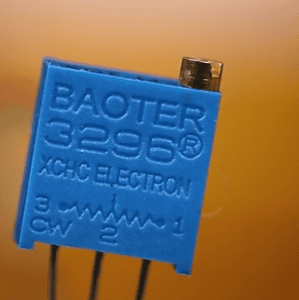
This one has a small pin diagram pressed into the case. On the top of this one we find the numbers “102” meaning 10 with 2 zeros after that, which is therefore a 1,000 ohms maximum resistance version.
These long horizontal versions have a screw on the side. This one has a wiring diagram on the case so that we know which pin is which.
Inside we find a resistive track and a conductive track held on a ceramic base. The wiper bridges across the two and is held by a slider. Adjusting the screw rotates the thread and that moves the slider and wiper forwards or backwards along the tracks, changing the resistance very precisely.
The resistance is indicated with this number, here it indicates a maximum of 1000 ohms resistance.
With all potentiometers, make sure to check the manufacturers datasheet for connection diagrams, rated power, voltage, number of uses and the type of taper. Many components will have a parts number printed on them you can search online to find the datasheet.
You can also get an engineering mindset mug to help support the channel, buy yours HERE.
We use potentiometers as voltage dividers or current limiters.
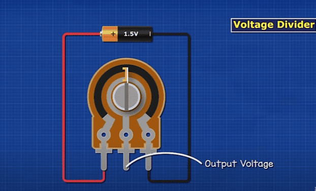
With a voltage divider, we connect the power supply across the two end pins, and the wiper connects to the centre pin. This pin provides our output voltage. If we connect our multimeter to this output and to ground, we can see the output voltage varies as we rotate the shaft.
If we use the resistance function and connect between the two outer pins, the resistance remains constant. We are measuring the total resistance of the track. But, if we connect from the left pin and centre pin, we can see the resistance varies. So we can use just part of the total resistance.
Here, the battery is providing 9 volts on the positive wire and the negative wire is 0 volts. So, when we connect them across the end pins, the voltage needs to drop from 9 to zero across this length. We can make that distance long or short, the same voltage drop still occurs, just at a different rate.
Lets say this track has 900 ohms of total resistance, we could divide that track into 9 segments, 100 ohms each.
The electrons will all flow through this track from one end to the other. So the current is going to be the same at any point along the track.

To find the voltage at any point, we just calculate the voltage drop. We are starting with 9 volts. Segment 1 has 100 ohms resistance, so the current multiplied by the resistance gives us 1 volt. But that means we have 8 volts remaining at this point. Segment 2 is also 100 ohms so it too causes a loss of 1 volt. But, it was only receiving 8 volts, so here we only have 7 volts remaining. That continues along until we reach the end with zero volts remaining. So, now we know the voltage drop at any point.
Now, we take our wiper arm and connect it to the track. This lets us move along and make use of the exact voltage we require. Because we only use part of the total resistance so we only use part of the total voltage drop.
This is great for signal and control applications but it’s not good for a power supply because as soon as we connect a load to the output, the resistance of the load creates a parallel path for current, so the voltage will reduce.
We can also use potentiometers for current control, we call this a rheostat. Potentiometers only have a small power rating, so larger current circuits require purpose made rheostats which look something like this, they are generally much larger and can handle much more power.
We just connect the power supply between one of the end pins and the centre pin. The electrons will flow from the battery, along the track and then out through the centre pin as this is the only exit available. Moving the wiper changes how far the electrons need to flow to reach the exit.
The voltage drop occurs over this distance, the further the distance, the more resistance the electrons encounter which reduces the current.
If we had a 900 ohm track, we could divide it into 9 segments. We connect the positive 9 volt to one end and the zero volt ground wire to the wiper. All the electrons need to flow through to the wiper. The voltage drop remains the same between these two points. No matter where we move it.
At segment 1, we are only using a small part of the total resistance, so the current is really high. At segment 2 the resistance has now doubled, so the current will half. The current continues to reduce the further we move along the resistive track until we reach the end, where the minimum current can flow.
Be careful though, if you move the wiper to the very start, there is little or no resistance so the battery will try to fully discharge resulting in a huge current flowing here.
We can use this circuit to control the brightness of an LED. Just connect an LED to a resistor of around 350 to 400 ohms, and then connect this to the potentiometer and use a 9 volt battery. It should look like this. When we turn the shaft we can control the current and that changes the brightness of the LED.
We need this resistor to set the maximum current for the circuit, and that’s just in case we move the wiper too far, otherwise a huge current will flow and it will just destroy the LED.
RGB LEDs are just 3 separate LEDs combined into one, a red, green and blue LED. So, if we control the brightness of each LED, we can create any colour we want. You can download my PCB file for free and order this yourself to make at home. Download it HERE.

