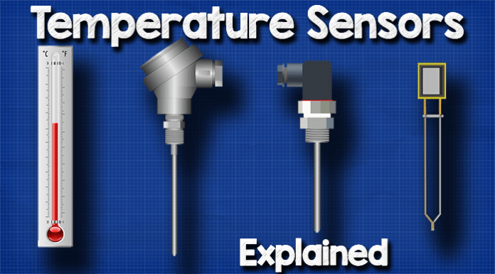
Temperature sensors explained. In this article, we’re going to be looking at contact temperature senors to understand the different types and the basics of how they work. We’ll look at the main types being the Thermometer, Thermocouple, Resistance Temperature Sensor and the Thermistor as well as a comparison of the technologies towards the end.
Scroll to the bottom to watch the FREE YouTube video tutorial
🎁 Start your free Danfoss temperature sensor eLesson – http://bit.ly/TempSensorDL
The Temperature Sensor eLessons available in Danfoss Learning will give you an understanding of the Danfoss temperature sensor program, the type designation system, which sensors are best suited for each application, and know how to select a sensor. You’ll also gain a deeper understanding of temperature sensor technology. Create a free Danfoss Learning account – http://bit.ly/TempSensorDL
How do we physically measure temperature?
We all know we can measure temperature using a thermometer. This is a very simple design used for hundreds of years. It’s simply a sealed glass tube which is partly filled with some liquid like Mercury or Alcohol. As heat is applied, the liquid expands and rises up the column.
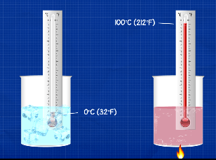
The height of the column is divided up and marked to correlate it with known temperatures, for example: at water boils 100°C (212°F), and it freezes as 0°C (32°F). As the liquids volume expands and contracts, we can easily read the temperature.
This method is easy for humans to use but it’s slow, it’s not the most reliable or accurate and we’re pretty limited on temperature range. We need a fast and accurate way to take digital temperature readings which allow computers and controllers to accurately monitor and autonomously control systems.
Thermocouple
The oldest way to accurate digital temperature measurements is to use a Thermocouple. If you have a hand held temperature probe or even a multimeter which can take temperature readings, it’s probably going to come with one of these. They are also built into solid cases a much more rugged design which is typically used for industrial installations.

With a Thermocouple we connect two different metals together at one end, and the other ends connect into a terminal block. Then we use a voltmeter to read the voltage difference between the two metals. The voltage here will be very tiny.
How does this work?
If we held a metal rod in our hand and place the other end into a flame, we know the rod will heat up and this heat will travel along the length of the rod to our hand. What’s happening here is the heat is exciting the atoms and molecules which form the materials structure.
The heat causes the molecules and the atoms to vibrate. This vibration is so tiny you can’t feel it in your hand. The excited atoms will allow their free electrons to move more easily and they will move towards the cooler end of the rod.
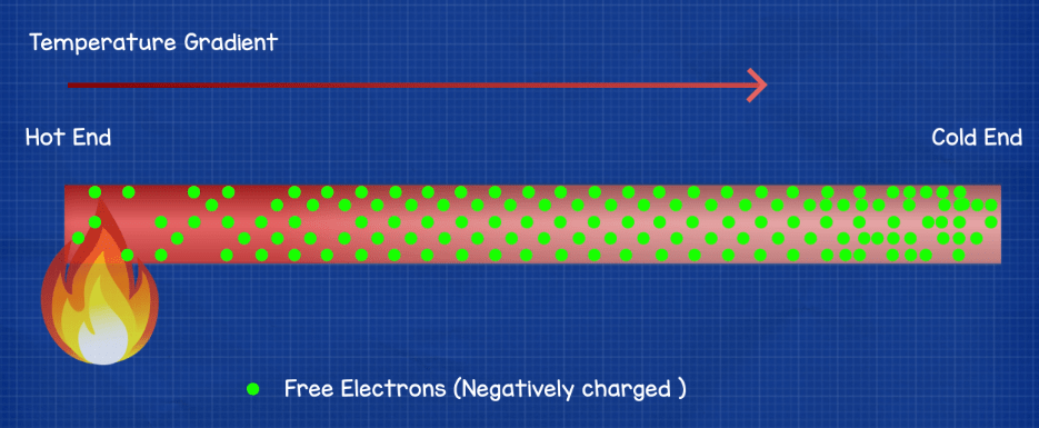
This only occurs because there is a temperature gradient, a difference in temperature from one end to the other. So at the cooler end we’ll have slightly more electrons than the hotter end and as electrons are negatively charged, we therefore get a slightly negative and positive charged ends of the rod.
Voltage is like pressure, when we measure voltage we’re measuring the difference or potential difference between two points. If you imagine a pressurised water pipe, we can see the pressure using a pressure gauge.
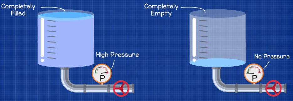
The pressure reading is comparing two different points also, the pressure inside the pipe compared to the atmospheric pressure outside the pipe. When the tank is empty the gauge reads zero because it has nothing to compare, both are the same pressure.
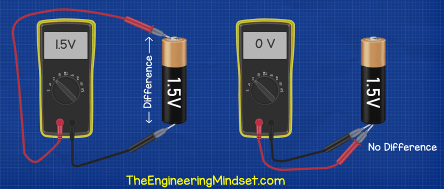
Same with voltage, we are comparing the difference from one point to another, if we read across a 1.5V battery we get a reading of 1.5V, but if we try to measure the same side we wouldn’t read any voltage. We can only measure the difference between two points.
Coming back to the thermocouple. If we connected two wires together of the same material, let’s say copper, and we applied heat to the end to create a temperature difference, then the electrons would scatter and build up at the cold ends. However, they would build up in equal amounts in each wire because they are the same material so both conduct heat equally and the temperature gradient will be the same. Therefore, our voltmeter wouldn’t be able to measure any difference.

However, if we connected two wires which were made of different materials, say copper and iron, then the two metals will conduct heat differently so their temperature gradient will be different. That means the electron build up at the cold ends will be different. So, we can connect a voltmeter to this and read a voltage difference.

To make this into a useful tool we just calibrate it by testing the device against known temperatures and mark down the voltages generated, then use a formula to tell the temperature from the voltage.
For this to work best, we should submerge the cold junction into an ice bath, that way we get a voltage with a reference relative to 0°C (32°F). Remember we same that with pressure in a pipe we are comparing it against the atmospheric pressure outside, that’s because we know the pressure outside the pipe, it’s atmospheric pressure which is 101.325 kPa or 1 Bar. So, for the voltage reading to be accurate we need to measure against something we know, therefore we use ice water because we know this temperature is a constant 0°C (32°F).

This method is used in many science labs, however, it isn’t very practical for most engineering applications so instead to improve the accuracy we leave the cold connections at equal ambient temperature and then we compensate for the difference by measuring the temperature of the connection and applying a formula to offset the error. To measure the temperature of the connection we often use an RTD temperature sensor which we will look at next.
Resistance temperature detector or RTD.
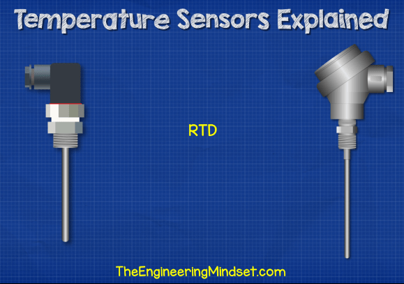
This is also a fairly simple design and probably easier to understand than the thermocouple. They usually come in these type of designs for engineering applications with rugged casing.
How do these work? Well, we know that electricity is the flow of electrons through a circuit. We’ve covered this in other tutorials, click here to learn about that in detail.
When we pass electricity through a material, lets say a copper wire, the material will have some resistance to the flow of electrons and we can measure this resistance with a multimeter. Different materials have different resistance levels.
The temperature of the material will change the resistance of a material. Most conductors will increase in resistance the hotter they become, that’s typical of metals. This occurs because as the atoms and molecules become excited they move around, so it’s harder for the free electrons to get through without a collision.
Using a formula known as Ohms law, voltage is equal to Current multiplied by resistance. Which means that as long as we keep the current the same, a change in resistance will cause a change in voltage. As temperature changes the resistance of a material, we can measure the voltage to tell the temperature.
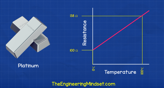
We use a material like Platinum which has a near linear resistance vs temperature gradient. We test the material again at known temperatures to obtain the graph. For example at 0°C (32°F) the material will have a resistance of 100 Ohms, and at 100°C (212°F) it has a resistance of 138.5 Ohms.
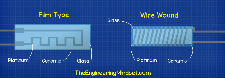
There are some different designs for these type but typically they’re either a film type where the platinum is coated onto a ceramic plate into a pattern and sealed in glass. Or it will be a platinum wire wound around a ceramic core, again sealed in glass for protection.
Thermistors
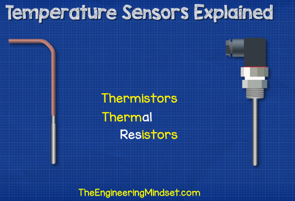
Thermistors have a few variations in design but they will either be a flexible version for portable use or a more rugged design for fixed installations.
A thermistor is just a thermal resistor. Meaning it’s an electrical resistor which changes resistance with temperature.
There are two types of thermistors, the NTC or negative temperature coefficient and the PTC the positive temperature Coefficient.
We saw earlier that the resistance of a metal typically increases as the temperature increases because the atoms start to vibrate which makes it harder for an electron to flow through without colliding.
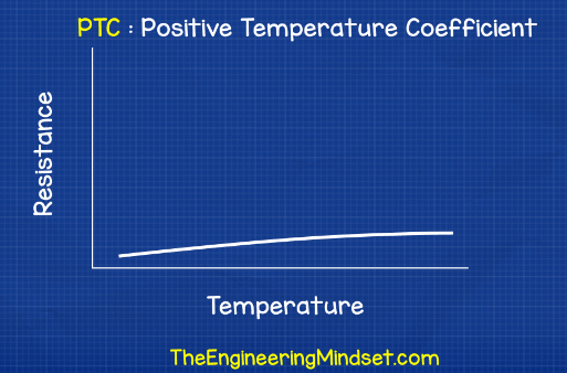
The PTC type thermistor behaves something like this, we call it positive because if we plotted the resistance with temperature then we get an upward trend showing an increase in resistance with temperature.
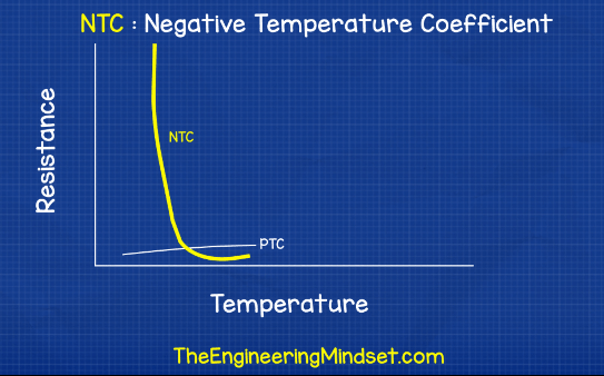
The other type is the NTC or negative temperature coefficient. With this type we use a semiconductor which behaves a little differently. As you might guess we call it a negative temperature coefficient because when we plot the resistance with temperature this type will actually decrease in resistance. This is to do with the structure of the atom and material.
If we look at a simplified atom of a metal first, we have the nucleus at the centre then a number of electrons all on different orbital shells. A conductor has 1-3 electrons in it’s outermost or valance shell. Each shell holds a maximum number of electrons and an electron has to have a certain amount of energy to be accepted into each shell. The electrons farthest away from the nucleus have the most energy. We need electrons to be able to move between atoms for a material to carry electricity.
Electrons are held in place by the nucleus but if they can reach the conduction band then they can break free and move. With the metal atom, the conduction band and the valance shell overlap so it’s easy for the electron to become free and move.
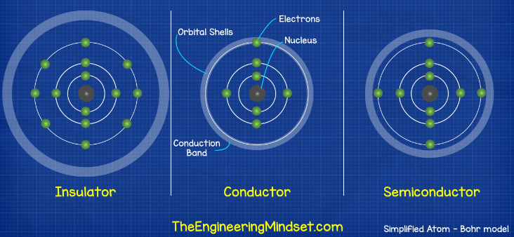
With an insulator the outermost valance shell is packed, there’s very little to no room for an electrons to join. The nucleus has a tight grip on the electrons and the conduction band is far away so electrons can’t reach it and escape. Therefore electricity can’t flow through this material.
However, with a semi conductor, there’s 1 too many electrons in the outer shell for it to be a conductor so it behaves as an insulator but the conduction band is quite close. If we heated the material up, some electrons will gain enough energy to make the jump and break free from the atom. As more heat is added more electrons move from more atoms and so the materials resistance decreases.

It’s basic construction is just a piece of semiconductor between two conductors and this is sealed with a protective coating.
Which type of temperature sensor is better?
They all have different pro’s and cons. There is no perfect fit, it depends what you need to use it for.
Consider that these are used for everything from water, steam ,air, gas, refrigerants, oil and they are used everywhere from engines, air conditioning systems, air compressors, heating systems, hydraulics, production lines etc.
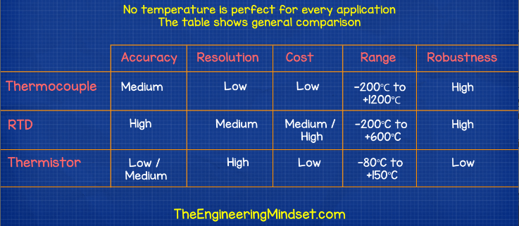
But I’ve put together a rule of thumb table to compare the different types. You can see they each have different ranges, accuracies and robustness which is going to be reflected in the price.





Well explained Evans, touched all the involved basics.
[…] LEARN MORE HERE: https://theengineeringmindset.com/temperature-sensors-explained/ […]