

Reversing valves for heat pumps. In this video we’re going to be looking at the four port reversing valve, which is used in heat pumps. This is a critical component in the heat pump system, and this is what allows the refrigerant to reverse its flow to provide both heating and cooling modes.
Scroll to the bottom to watch the YouTube tutorial video on reversing valves
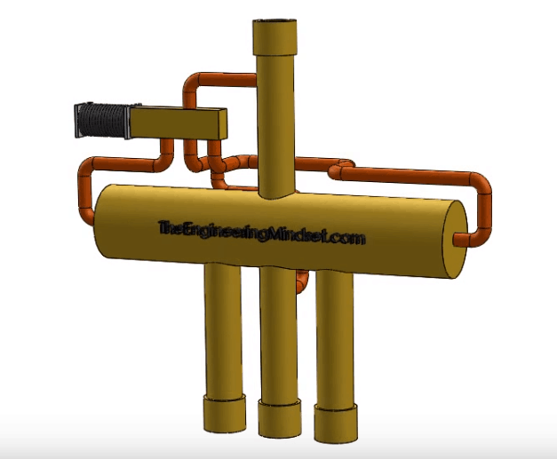
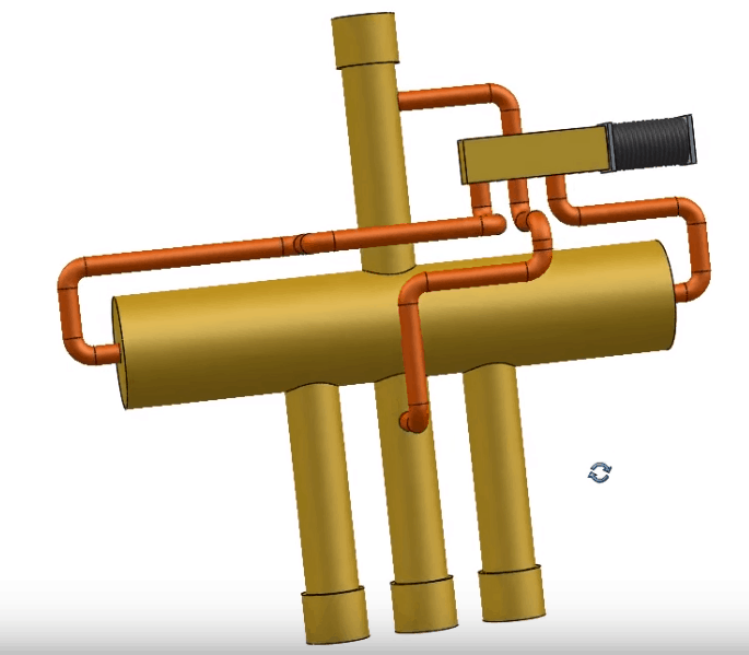
Above is a 3D model of a reversing vale which we will use to explain the working principles of the valve. As you can see, in the centre is a cylinder which is the valve body. Running from this perpendicular to the valve body are 4 pipes, 3 along the bottom and one on top. These pipes are the points of entry/exit for the refrigerant.
Behind the main body are some capillary tubes which connect to opposite ends of the main body as well as the upper and lower pipes. Coming off the capillary tubes is a solenoid valve and solenoid coil. We’re going to discuss the purpose of all of these parts.
Looking inside the reversing valve with a section view, above. We see inside the central valve body a black “U” shaped bodied object which is mounted inside a metal slider. The slider will move from side to side and move the U shaped body which is used to direct the refrigerant around the refrigerant circuit.

To move the main body slider, we use another sliding “U” shaped body which sits within the solenoid valve. The solenoid valve slider is forced by a spring into the normal position but once the solenoid coil in energised it will create a magnetic field which will pull the slider to the other side of the valve, allowing the refrigerant to change direction within the solenoid. This will impact the slider within the main body.
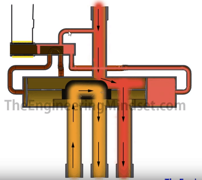
When the solenoid coil is energised, it will create a magnetic field which will pull the solenoid slider over to the left side. The hot refrigerant, from the compressor, will enter via the top pipe and flow into the central main valve body. Some of this high pressure will flow into the capillary tube, through the solenoid and down into the right most side of the main valve body. This will force the main slider over to the left hand side. The hot refrigerant which is entering via the top pipe will therefore flow into the main valve body and exit via the lower left pipe. From there it will head to the outdoor unit where it will reject the systems heat and go off to provide cooling.
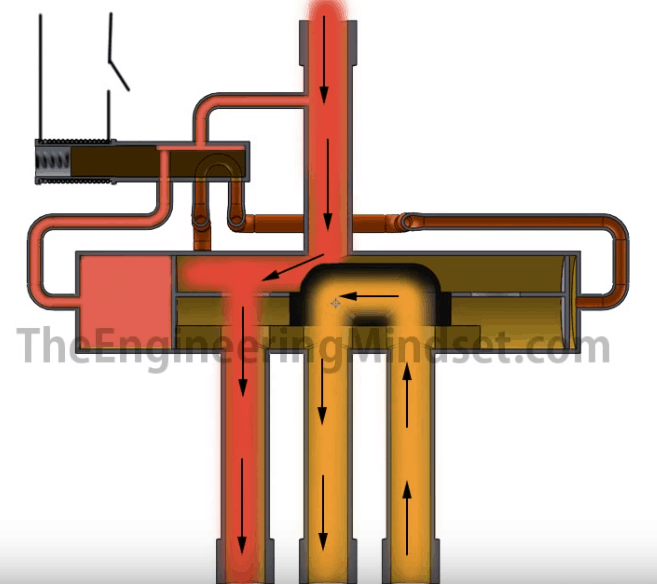
When the reversing valve operated in heating mode. The solenoid coil in de-energised and so the internal spring forced the solenoid valve slider over to the right. The high pressure refrigerant will enter via the top pipe and head towards the main valve body. Some of the refrigerant will flow into the solenoid via the capillary tube. This will then flow into the left most side of the of the main valve slider, forcing the main slider to move to the right most side. The hot refrigerant then enters via the top pipe and flows out via the lower left pipe and off into the indoor unit to provide heating.
When the reversing valve operates in heating mode. The refrigerant will leave the compressor and head to the reversing valve. It will enter via the top pipe and exit via the lower right pipe. From there it heads to the indoor unit where it will provide heating to the room. It will then flow along to and through the check valve, the next check valve will not let it pass so the refrigerant will flow instead through the expansion valve. From there it will flow into the outdoor unit and pickup more heat. It will then flow into the reversing valve again but the main slider will direct it back into the compressor.
When the revering valve operates in cooling mode. The refrigerant will leave the compressor and head to the revering valve. It will be diverted out the lower left pipe and flow into the outdoor unit where it will give up some of it’s thermal energy. It the flows through the check valve but the second check valve won’t allow it to pass through so it’ll go via the expansion valve and into the indoor unit to pickup the unwanted heat and thus providing cooling. From there it flows back into the revering valve where it’s directed back into the compressor to complete he cycle.
For more on how heat pumps work, click here


")

")


")
That’s cool that the refrigerant is controlled by the solenoid valve slider. I imagine that make sure the solenoid pump works properly is an important part of making this process work. If I worked in engineering, I’d love to understand more about solenoid pumps!
[…] but in this article, we are going to be looking at a typical air source heat pump. These use a reversing valve to allow both heating and cooling […]
[…] reversing valve is switched positively from end-to-end by pressure differential in the system (see TheEngineeringMindset.com for a detailed explanation). Since the compressor was producing very little flow and there was […]