

Learn how servo motors work in this tutorial. Exclusive offer, VPN just $1.98/m + 4 months extra FREE:👏 https://www.privateinternetaccess.com/TheEngineeringMindset
Scroll the bottom to watch the YouTube video

This is a servo motor; it’s used in precision engineering applications and uses internal electronics as well as mechanical gears to achieve this. So we’re going to learn how they work and how to program one in this article which is sponsored by Private Internet Access. You can get a 3 year subscription with 4 extra months for free for only $1.98 per month using THIS LINK. Their VPN service helps safeguard your online privacy and can protect up to 10 devices at a time to let you browse the web with increased anonymity. It works with all major streaming services. It works on windows, mac, android, iOS and even Linux. They offer a 30 day money back guarantee so Do check them out HERE.
What is a Servo Motor?
A servo motor looks something like this. It converts electrical energy into mechanical energy. This type of motor is used for precise control, and we can connect different attachments to achieve that. We control the position of a servo motor using a controller. So, we often find it used in robotics, automation and even the steering for remote control cars.
Usually when we connect a DC motor to a power supply, it just rotates constantly. But a servo motor is different. These will not instantly rotate. Instead, these are sent signals which tell the motor exactly how far to rotate.
Typically, the motor will rotate just 180 degrees but we can get smaller or larger values. These are closed loop type. There’s usually a pin inside to physically stop the motor rotating further. Some don’t have this and are able to rotate a full 360 degrees, these are open loop type. Closed loop provide the best control and are more commonly used, so we will focus on these type in this article.
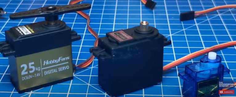
On the side of the servo motor, we usually find a weight value. This is not the weight of the motor. It represents the torque of the motor, or how much force it can apply. This small motor has a rating of 9 grams, this larger one has a rating of 25 kilograms. This is how much force the servo motor can apply to a lever. We usually find this measured in kilogram centimetres or ounce inches. What does that mean?
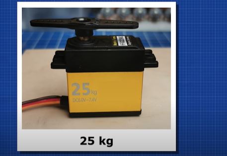
Well, for example this servo motor is rated for 25kg so at 1 centimetre from the shaft, it can support 25kg, but at 2 centimetres it can only support 12.5kg and at 3 centimetres it can only support 6.25kg
We can find more information on the datasheet. In this example, we see it can be connected to a supply of between 4.8V and 7.2V.
The higher the voltage applied, the higher the torque will be, so the stronger the motor will perform. But, as we can see, the motor has limits and it will stall if we exceed these limits.
When the motor stalls, we see the current dramatically increases.
The operating current depends on the load and the voltage. The motor consumes more power when moving, it uses very little to hold it’s position.
The high the voltage applied, the faster the motor will rotate. We measure the rotation in seconds taken per 60 degrees rotation.
The physical size of the servo motor increases with the torque rating. That’s because it needs larger gears and a larger electrical motor to achieve this. Let’s look inside one to see the main parts and then understand how it works.
We have also covered stepper motors and DC motors previously, do check them out here: Stepper Motors and DC Motors
Main Parts
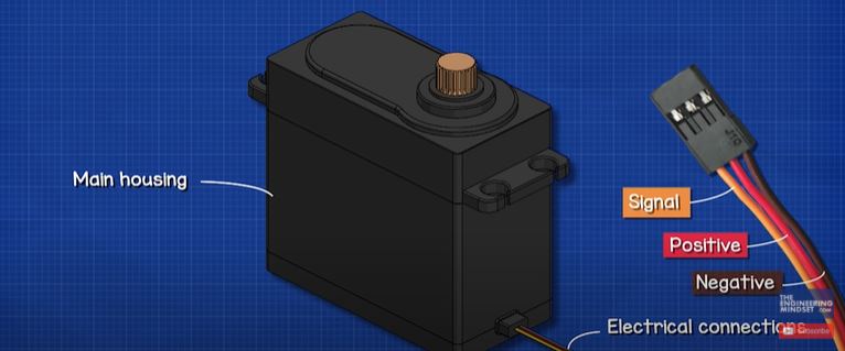
When we look at a servo motor we see the main housing with the electrical connections entering the side. In this case the red wire is the positive voltage wire, the brown wire is ground and the orange wire is the pulse width modulation signal wire, these colours do vary by manufacturer. On the top we find a small splined gear. We can connect various attachments to this, to make use of the rotation.
Inside the unit, we first find a number of gears and these are supported by some bearings. On one side we have the output and on the other we have the input. The input is connected to a DC motor which drives the gears. This is known as a compound gear train. The gears are arranged in this way to ensure a compact design. The motor has a high rotational speed but a low torque, so the gears help convert this into a low speed but high torque output. In this example, there is an 11 tooth pinion gear on the motor, this connects to a 61 tooth gear which is directly joined to a 12 tooth gear. This connects to a 48 tooth gear which is directly connected to a 13 tooth gear. This connects to a 47 tooth gear which is joined to a 13 tooth gear and this connects to the final gear which has 42 teeth.
So, for this example, using some arbitrary numbers if the input is 259 RPM with 1 newton meters of torque, then the output will be 1 RPM but 259 newton meters of torque. Therefore, we have converted high speed low torque into low-speed high torque. There are losses which I’ve purposely ignored for this example.
We have covered how to calculate this in our previous video on gear trains, do check that out HERE.
The DC motor is connected to a small circuit board inside the unit. This controls the rotation of the motor as well as the direction of rotation.
Also connected to the circuit board is a potentiometer. This connects to the output gear of the servo. This is just a variable resistor, as the final gear rotates, it rotates the potentiometer which changes the resistance and the circuit board reads this to know the position of output.
Let’s see how this works. But first, where have you seen these motors used or what would you use them for. Let me know in the comments section.
How it Works
A controller sends a signal to the servo motor, which determines which position it should rotate to.
The controller could be something like an Arduino, or even a simple servo tester. This is a pulse width modulation signal. Which means it sends pulses of voltage down the wire. The width of the pulse can be varied. It’s similar to if we pressed a switch to turn a light on and off, the longer we press the switch, the longer the pulse of electricity.
These pulses are sent every 20 milliseconds, so we have around 50 pulses per second. Or, 50 Hertz. We can use an oscilloscope to see these pulses, for example this is the signal sent by an Arduino. And this is the signal from the servo tester.
The width of the pulse determines the position of the servo. If we send a wide pulse, the servo moves to the left, if we send a small pulse it rotates to the right. We can move to any position between these two points by simply changing the pulse width. As long as the pulse remains the same, the motor will hold it’s position. As soon as there is a change, the servo motor moves.

We can see here that when I rotate the dial on the servo tester, it’s changing the width of the pulse and the servo motors position changes to align with the signal. As I increase the voltage from the power supply, the height of the pulse also changes, put the position of the motor remains the same.
If we use an Arduino board, we can run a program to control the position. Or we can even use a potentiometer to control the position. We will learn how to build this later in the article.
The signal enters the servos circuit board and is converted to a voltage. It passes through a comparator, and then to a motor driver. The motor driver controls the rotation of the DC motor. It uses an internal H bridge circuit to control the direction of rotation, either clockwise or counter clockwise to get to the required position.
This rotation causes the gears to rotate which causes the final gear and servo arm to also rotate. Connected to the final gear is the potentiometer.
You might recognise a potentiometer to look more like this, they essentially work the same. The resistance increases and decreases between a minimum and maximum value as the arm is rotated.
You can see here that the multimeter is measuring the resistance and when I turn the shaft, the resistance changes.
This acts as a voltage divider. If we apply a voltage across the potentiometer, for example 5 volts, we can then measure the change in voltage due to the varying resistance, this change is proportional to it’s position. When the arm is turned fully to the left, the voltage is 5 volts, at the centre it is 2.5 volts and when turned fully to the right it is 0 volts.
The potentiometer is also connected to the comparator of the internal circuit board and the voltage is monitored to provide feedback. We know that the resistance changes between a minimum and maximum value as the potentiometer dial is turned, so the comparator is going to compare the voltage of the potentiometer to the voltage from the controller signal. If there is a difference, then the motor will turn until the difference is close to zero. Then the servo knows it is in the correct position so it waits there until there is another change.
We will learn how to control a servo motor in just a moment, but I just want to remind you to check out our sponsor Private internet access using THIS LINK where our viewers can get a 3 year subscription with 4 extra months free for just 1 dollar 98 per month, and enjoy a safer internet access across 10 devices.
Worked Example
We’re going to learn how to program an Arduino to control a servo using a potentiometer. For this you’ll need an Arduino, a bread board, a servo motor, a potentiometer, some wires and a power supply.

First, connect a wire from the 5V port to the positive rail of the breadboard. Then connect another wire from the ground port to the ground rail. Now connect from the 5V rail to the left side of the potentiometer. Then connect the right side to the ground rail. Then connect the centre pin to port A0. Next connect from the 5V rail, to the servo motor. Then connect the ground wire to the servo and finally connect the signal wire to port 9 of the Arduino. The circuit should look something like this.
So, now we need to connect the Arduino to the pc and write the code. You can download my Arduino code for free HERE.
The basic code is very easy, we just type this at the top
#include <servo.h>

This tells the Arduino that we are using commands from the premade servo library.
Then we need to create an object, basically we declare the name of the servo so we can tell it what to do, I’ll call this Servo1;

Then we tell the ardunio which of its pins is connected to the servo motor, in our case we have pin 9, so we type that.
int servoPin = 9;

Now, as we are using an external potentiometer as an input device to control the servo motor, we need to declare this also. So we type this, which just lets the Arduino know which port it will receive a signal.
intpotPin = A0;

Then we type this line of code in
void setup() {
Servo1.attach(servoPin);}
This just links the named servo to the pin which we also declared.

Next we type this code in
voidloop() {
intreading =analogRead(potPin);
intangle =map(reading,0,1023,0,180);
servo.write(angle);
This is saying we need to read the value from the analogue input of the potentiometer. Which is connected to port A0[PE1] .

The Arduino reads the voltage through this pin, but it doesn’t understand voltage, because this is an analoge signal port. So it will generate a number between 0 and 1,023, depending on the voltage. When the potentiometer is all the way to the left, it receives the full voltage so it is 1023. When it is turned all the way to the right, it is at 0 volts, so we read 0. The value changes as we turn the dial.
The servo doesn’t understand these number though. It want’s to know a rotational degree between 0 and 180 degrees. So this is creating a map or conversion scale, to say that if the signal is zero then the position is 0 degrees, if the signal is 1023 then the position should be 180 degrees.
The final line just sends the information to the servo, it writes to the servo to let it know what to do.
So then we send this code to the Arduino and shortly after, we will we able to control the servo position with the potentiometer. Once you understand this, you can make more advanced circuits.


")

")