Scroll to the bottom to watch the YouTube tutorial
Learn the basics of the typical circulation pump to understand how it works and where we use them.
Check out statesupply.com who have kindly sponsored this article. Here you can find which circulating pumps are available, shop for parts, or speak to knowledgeable product specialists about top pump brands like Bell & Gossett and Taco. Simply click here to find out more.
State Supply is your source for steam and hydronic heating system components, such as steam traps, valves, controls, and pumps (including the industry’s top brand like Bell & Gossett, Taco, and more). Visit www.statesupply.com or call us toll-free at 877-775-7705 for an unparalleled selection of products, knowledgeable experts, and outstanding customer service.
Check out circulating pumps ➡️ https://www.statesupply.com/pump/hydronic
View pump repair & maintenance videos ➡️ https://www.youtube.com/statesupply
Download this guide ➡️ https://www.statesupply.com/boiler-inspection-checklist
What is a Circulating Pump and Where are They Used?

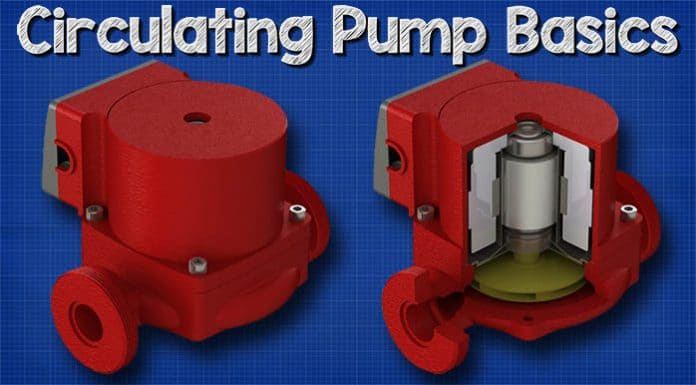
Circulating pumps come in many shapes, colours and sizes but they typically look something like these. These pumps are inline centrifugal type pumps which means their inlet and outlet are aligned and the method of moving the water is via centrifugal forces.

We’re going to find these pumps used to circulate hot water around a heated water circuit so that when we open a tap, we almost instantly have access to hot water. Otherwise every time we opened a tap we would have to wait for hot water to flow through the entire system.

In hydronic heating systems we will also find these pumps used to circulate heated water between the boiler and radiators or other types of heat exchangers.

We might also find circulating pumps used in larger heating systems to supply heat to different parts, or zones, within a building.
Main Parts of a Circulating Pump

The circulating pump consists of two main parts, the pump and the motor.
The motor is an induction type motor which allows us to convert electrical energy into mechanical energy. This mechanical energy is used to drive the pump and move the water.

When we look at the pump casing, we have an inlet, as well as an outlet. The pump pulls water in through the inlet and pushes it out through the outlet. Typically, there will be an arrow on the casing to identify the direction of flow so you know which is the inlet and outlet.
As this is an inline pump the inlet and outlet are aligned concentrically , this is useful because we could potentially cut a section of pipe out, from a hot water system, and install a circulating pump within this space without having to alter the pipework like we would need to for a standard centrifugal type pump.

This is still a centrifugal type pump though so the water needs to enter the pump via the eye of the impeller. To achieve that, the inlet follows this curved path which sweeps around into the impeller.

This part is the pump casing. It has a channel inside known as the volute. After the water exits the impeller it will collect in this channel and make its way to the outlet. We’re going to see that in more detail later in the article.

Next, we find the impeller, which sits within the pump casing and is surrounded by the volute channel. The impeller rotates and imparts a centrifugal force on the water which pushes it out of the pump and through the pipes.

Behind the impeller we have the backplate. The backplate acts like a barrier and keeps the flow of water within the pump case. The backplate also holds one of the bearings for the shaft to ensure a smooth rotation. Attached to this we will also find a rubber seal to prevent leaks.


Next we’re going to find the shaft and rotor. The rotor is attached to the shaft and the shaft is attached to the impeller. When the rotor rotates so will the shaft and impeller. That’s the driving force of the water within the pump.

The rotor sits within the rotor can. The rotor can, provides a physical barrier which prevents any water coming into contact with the electrical circuit of the induction motor.

Surrounding the rotor can we have the inductor motor. This consists of a number of coils of copper wire which are tightly packed into the stator. The coils and stator are stationary and do not rotate. Electricity flows through the coils within the stator, this will create a rotating electromagnetic field which causes the rotor to turn.

Protecting the stator and coils we have the motor housing. On the side of the motor housing we will find the electrical terminal box. On the front of this we have the speed selector switch, this allows us to manually change the rotational speed of the motor between low, medium and high which changes the flow rate of the pump.

Inside the terminal box we have the speed selector switch. We also have the ground, neutral and line terminals which allow us to connect the pump to our power supply. There’s usually also a capacitor inside with this type of pump, the capacitor is vital to the operation of the pump, so we’re going to look at that in detail just shortly.

Motor Windings and Capacitor
The electrical motor within the circulating pump is a single phase alternating current induction motor.

Electricity is the flow of electrons through a wire. We have DC or direct current which we get from supplies such as batteries, and in this type of electricity the electrons flow in just one direction from the negative to the positive.

But the electrical supplies in your homes and places of work will be a different type of electricity known as alternating current. With alternating current, the electrons alternate in direction and flow forwards and backwards repeatedly.

As electricity flows through a wire it generates an electromagnetic field. When the electrons change direction, the magnetic field continuously expands and contracts. By wrapping the wire into a coil we generate a much stronger electromagnetic field.

When a wire is wrapped into a coil, we call this an inductor. When we apply an alternating current, the magnetic field expands and collapses, each time it expands and collapses the north and south polarity of the coil reverses. We need this expanding and collapsing magnetic field to create rotation.

To form the motor we wrap the wire into two coils within the stator to create a large electromagnetic field. If we place a rotor in the centre of this magnetic field, the rotor will align with the magnetic field and then it becomes stuck. To spin the rotor, we need a rotating magnetic field. If we took some magnets and carefully timed them to interact with the rotor we could achieve this, but it’s not very practical.


In larger motors, we create the rotating magnetic field using more phases, because the electrons flow forwards and backwards at a different time in the two phases, which will therefore create another magnetic field at a different time. However, this type of pump has only a single-phase connection, so we will instead use a capacitor to create a fake 2nd phase.
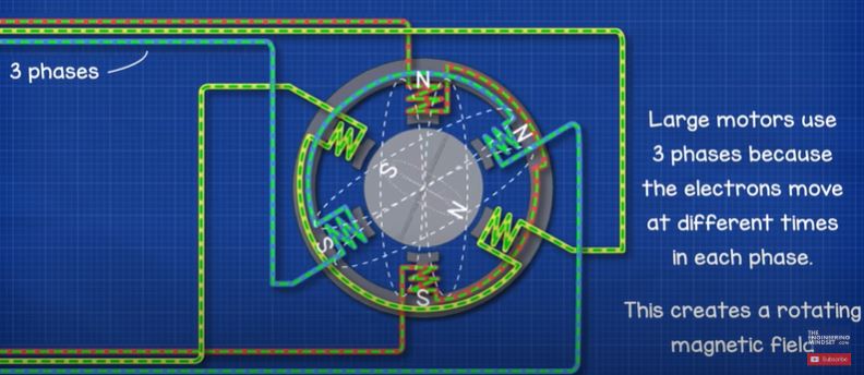
We therefore insert a second coil into the stator 90 degrees rotation from the first coil. The two coils are wired in parallel, but the second coil has a capacitor connected in series with the coil.

Electricity doesn’t pass through capacitors. The circuit is broken inside a capacitor to form two walls. The two walls inside are very close to each other so electrons can build up on these walls and also be released from here. Therefore, the capacitor is something like a storage tank or a diaphragm. When the supply of electricity moves in one direction, the capacitor will store electrons. When the electricity supply reverses direction, the capacitor will release electrons
This way we have electrons flowing through different coils at different times, this will create our rotating magnetic field. The capacitor has to be sized correctly to achieve this though.
We have covered the basics of capacitors in detail in a previous article, do check that here.
Multi-Speed Motor Windings
Typically, we have a switch on the side on the motor terminal which allows us to change the speed of the motor and thus the pump flow rate as well as head pressure.

Inside the motor, the run coil will have various connection points, or there might even be a number of different coils. The switch is used to connect onto these different points and effectively change the length of the coil which the electricity needs to pass through.

You might be wondering why does the low setting have a longer coil than the high setting.
When we pass an alternating current through an inductive coil, the magnetic field it generates interferes with the electrons trying to pass through it. A force known as inductive reactance opposes the change in current.

When we increase the length of the coil, the inductive reactance also increases and this makes it harder for the current of electrons to flow through. As the current has therefore reduced, the electromagnetic field also reduces, this reduces the speed and torque of the motor.

As we move to the lowest setting, the inductive reactance is at it’s maximum, the current is reduced and the motor rotates slowly.

When we move to the high setting, the inductive reactance is at its minimum so the current is high and the rotor rotates much faster.
We have covered multi-speed pumps and how to read their pump charts in our previous article. Do check that out here.
How Does a Circulating Pump Work?
So how does the circulating pump work. First of all, water from the hot water system enters the pump via the inlet and enters the eye of the impeller, this water will be trapped between the blades of the impeller within the pump housing.

Electricity enters the terminal box and flows through the motor windings, the capacitor helps create a rotating magnetic field and this magnetic field forces the rotor to spin. Attached to the rotor is the shaft. The shaft runs from the motor and down into the pump housing where it connects onto the impeller.
As the rotor rotates, so does the shaft and impeller. As the impeller rotates it imparts kinetic energy or velocity into the water and this moves outwards.
Water increases in velocity and kinetic energy as it reaches the edge of the impeller.
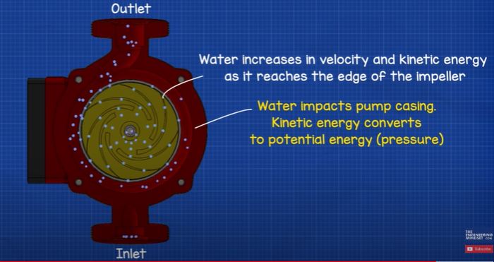
By the time the water reaches he edge of the impeller it has reached a very high velocity. This high-speed water fly’s off the impeller and into the volute where it hits the wall of the pump casing.
This impact converts the velocity into potential energy, or pressure.
Water impacts pump casing. Kinetic energy converts to potential energy (pressure).

As the water moves outwards and off the impeller it’s going to create a region of low pressure at the centre which pulls more water in and so a flow develops. The volute channel has an expanding diameter as it spirals around the circumference of the pump casing. As this increases, the velocity of the water will decrease, resulting in the pressure increasing.
More water follows behind; a flow rate develops. Diameter of volute channel expands; this causes the water velocity to decrease which increases the pressure.

The expanding channel therefore allows more water to keep joining and converting into pressure.

So, the discharge outlet is therefore a higher pressure than the suction inlet. The high pressure at the outlet allows us to force water to circulate through pipework and be drawn off when and where it’s needed. Ok guys that’s it for this video but to continue your learning checkout one of the videos on screen now and I’ll catch you there for the next lesson. Don’t forget to follow us on facebook, Instagram, twitter, linkedin as well as the engineering mindset .com











good, well explained in technical terms
Thanks, for the information, helpful for myself to do a recheck on my thoughts of Pump technology and circulation!!