
Turn Almost‑Empty Batteries into Light
The Joule Thief is a deceptively simple electronic circuit that demonstrates one of the most important ideas in electrical engineering: energy can be transformed, stored, and released in powerful ways using magnetism.
With just a handful of components, the Joule Thief allows a single low‑voltage AA battery even one most people would consider dead to power a white LED that normally requires more than 3 V. It does this by converting steady DC power into rapid, high‑voltage pulses using inductors, transistors, and electromagnetic principles first explored by Michael Faraday nearly 200 years ago.
What Is a Joule Thief?
A Joule Thief is a self‑oscillating boost converter. In simple terms, it:
- Takes energy from a low‑voltage source (≈0.7V–1.5 V)
- Stores energy briefly in a magnetic field
- Releases that energy as short, high‑voltage pulses
- Uses those pulses to drive loads that would normally be impossible
In this project, those pulses are used to drive a white LED, making the effect instantly visible and easy to understand.
How the Joule Thief Works (Conceptual Overview)
The Joule Thief operates by exploiting rapid changes in current and magnetic fields rather than relying on steady voltage levels.
1. A Small Current Starts Everything
When power is applied, a very small current is allowed to flow into the base of the transistor through a resistor and one winding of the toroidal inductor. This initial current is tiny, but it is enough to partially switch the transistor on.
This is a critical idea: a small current can control a much larger one.
2. Magnetic Energy Is Stored
As the transistor begins to conduct, a larger current flows through the second winding of the toroid. Any current flowing through a wire generates a magnetic field, and when that wire is wound into a coil, the individual magnetic fields combine into one stronger field.
The ferrite core concentrates this magnetic field, allowing energy to be stored efficiently. As long as the current is increasing, the magnetic field is growing and storing energy.
3. Faraday’s Discovery Comes into Play
Because the magnetic field in the toroid is changing, it induces a voltage in the second winding. This is the phenomenon of mutual inductance, first observed by Michael Faraday in 1831.
The induced voltage briefly adds to the original base current, pushing the transistor further on. This allows even more current to flow, which strengthens the magnetic field even more.
This positive feedback loop happens extremely quickly.
4. Core Saturation Ends the Party
The ferrite core cannot store unlimited energy. Once it becomes saturated, the magnetic field can no longer increase.
At that instant:
- The induced voltage disappears
- The transistor loses its base drive
- The transistor switches off almost instantly
5. Stored Energy Is Released as a Voltage Spike
Inductors resist sudden changes in current. When the transistor switches off, the magnetic field collapses rapidly and releases its stored energy.
As this collapse occurs, the circuit generates a very large voltage spike, often many times higher than the original battery voltage. This happens because the inductor is attempting to force current to continue flowing, even though the transistor has suddenly blocked the main current path.
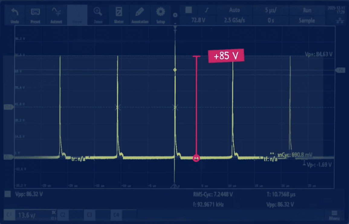
If the LED is not connected, this voltage spike has nowhere easy to go. When measured with an oscilloscope, it appears as a sharp, narrow peak that can reach surprisingly high voltages relative to the supply. (+80V in our tests) These spikes are brief, but they clearly demonstrate how low-voltage energy can be transformed into high-voltage pulses.
In a practical circuit, these spikes must be managed carefully, as excessive voltage can stress or damage components.
6. Light from a “Dead” Battery
When an LED is connected across the output, it provides a controlled path for this energy. The voltage rises until it reaches the LED’s forward voltage, at which point the LED conducts and converts the electrical energy into light. So the spike will no longer reach e.g. 80V as the LED will cap it at around 4V, when it starts to conduct and allow current to pass through.
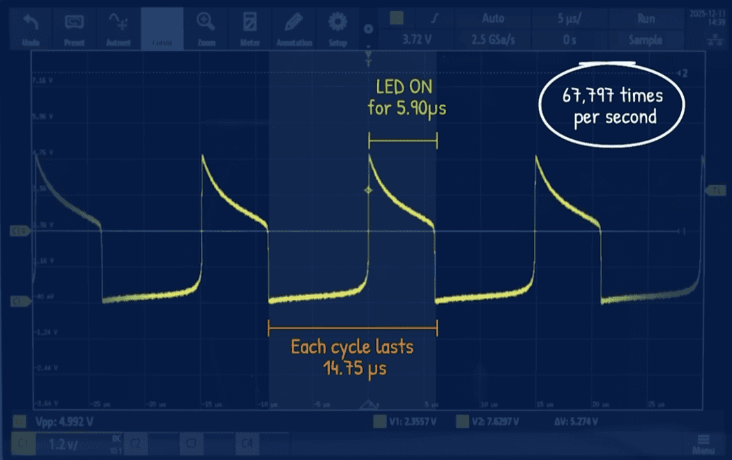
This entire process repeats hundreds of thousands of times per second. Although the LED is technically flashing, the pulses are so fast that the human eye perceives a steady glow.
What You Will Learn
By building and experimenting with this kit, you will gain hands‑on experience with:
- Electromagnetic induction and magnetic field storage
- Self‑inductance and mutual inductance
- Transistor switching and current amplification
- Core saturation and energy release
- Why inductors generate voltage spikes when current is interrupted
- How boost circuits work at a fundamental level
This is not a black‑box module. Every part of the circuit is exposed, measurable, and explainable.
How the Project Is Structured
The Engineering Mindset Joule Thief Kit is designed as a two‑stage learning experience:
1. Prototype First (Breadboard)
You first build and test the circuit on a breadboard. This allows you to:
- Verify correct operation before soldering
- Experiment safely
- Understand component placement and orientation
- Learn how to wind and test a toroidal inductor
2. Final Build (PCB)
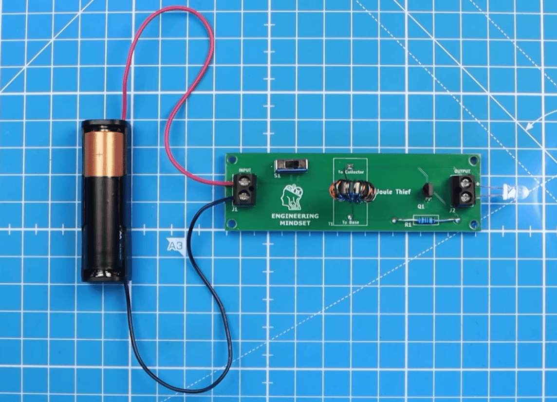
Once the prototype works correctly, you assemble a permanent version on the supplied printed circuit board.
The PCB is clearly labelled with:
- Component outlines
- Reference designators
- Polarity and orientation markers
The result is a robust, professional‑looking circuit suitable for demonstrations, education, or further experimentation.
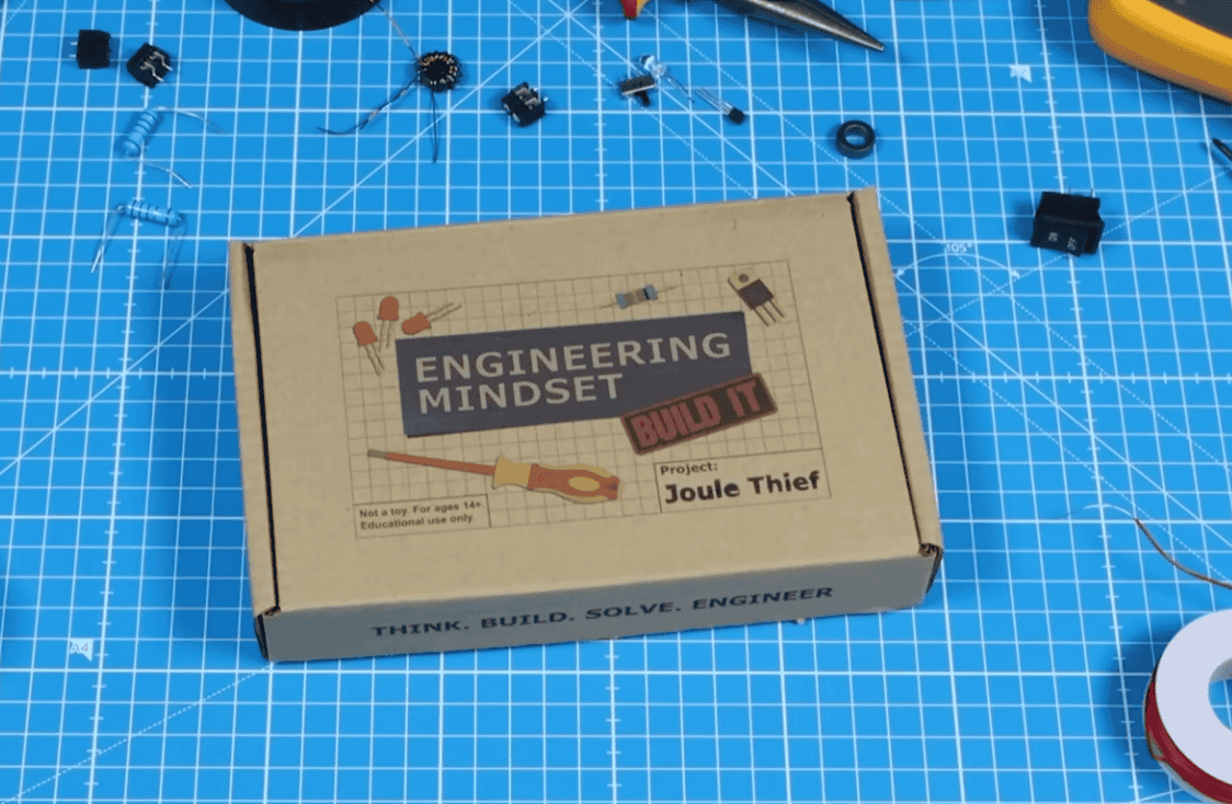
What’s Included in the Joule Thief Kit
Each kit contains all electronic components required to complete the projects.
- Custom Engineering Mindset PCB
- Ferrite cores
- Enamelled copper wire
- NPN transistors
- Resistors
- White LEDs
- Switches
- Terminal connectors
- Breadboard
- Jumper wires
- Battery holders
- Sandpaper for enamel removal
- Batteries
Some hand tools and soldering equipment are required but not included in this kit.
Safety & Intended Audience
- Recommended age: 14+
- Adult supervision required for soldering
- Contains small parts – Choking hazard
- Soldering involves heat and potential burn risk
- Eye protection and ventilation are recommended
This kit is an educational electronics project, not a toy.
Assembly Instructions & Documentation
A full paper based step-by-step assembly instruction guide is included with the kit along with a QR code to a step-by-step video instruction tutorial to build the kit.
If you have purchased the kit and require a copy of the manual, or a link to the video, please contact us with your order number.
Buy the Joule Thief Kit
If you want the complete learning experience from prototype to finished PCB the easiest way is to purchase the official kit.
👉 Buy the Joule Thief Kit here: https://engineeringmindset.store/en-gbp/products/joule-thief-board
Everything arrives in one box, carefully selected and tested to work together.
Want to learn how each component works?
Please see our free and highly detailed Youtube video about how each component works to form the circuit.


")

")

