Have you ever wondered how multispeed pumps work? In this article, we’ll explain how multispeed pumps work.
Scroll to the bottom to watch the YouTube tutorial.
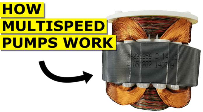
To form the motor we wrap the wire into two coils within the stator to create a large electromagnetic field. If we place the rotor in the centre of this magnetic field, the rotor will align with the magnetic field and then it becomes stuck. To spin the rotor we need a rotating magnetic field however, the circulating pump we’re looking at only has a single phase connection. So we will instead use a capacitor to create a fake second phase. We therefore insert a second coil into the stator which is 90 degrees rotation from the first coil. The two coils are wired in parallel but the second coil has a capacitor connected in series with the coil. Electricity doesn’t pass through capacitors. The circuit is broken inside a capacitor to form two walls. Therefore the capacitor is something like a storage tank or a diaphragm. When the supply of electricity moves in one direction, the capacitor will store electrons. When the electricity supply reverses direction, the capacitor will release electrons. The way we have electrons flowing through different coils at different times. This will create a rotating magnetic field. The capacitor has to be sized correctly to achieve this though.
We have covered the basics of capacitors in detail in our previous article, you can check that out HERE.
Multi-speed Motor Windings
Typically we have a switch on the side of the motor terminal which allows us to change the speed of the motor and thus the pump flow rate, as well as the head pressure. Inside the motor the run coil will have various connection points. Well there might even be a number of different coils. The switch is used to connect onto these different points, and effectively change the length of the coil which electricity needs to pass through. Now I know some of you will be wondering why does the low setting have a longer coil than the high setting? When we pass an alternating current through an inductor, the magnetic field it generates interferes with the electrons trying to pass through it. A force known as inductive reactants opposes the change in current. When we increase the length of the coil, the inductive reactants also increase and this makes it harder for the current of electrons to flow through. As the current has therefore reduced, the electromagnetic field also reduces. This reduces the speed and torque of the motor. As we move to the lowest setting, the inductive reactance is at its maximum. The current is reduced and the rotor rotates slowly. When we move to the high setting the inductive reactance is at its minimum. So the current is high and the rotor rotates much faster.
We have covered multi-speed pumps and how to read their pump charts in our previous article, check it out HERE.

