This article explains how centrifugal pumps work. Centrifugal pumps are used to transfer fluids and other materials in a wide variety of applications. This article is a helpful primer on the how’s and whys of centrifugal pumps, and is useful if you’re interested in learning more about this type of pump.
Scroll to the bottom to watch the YouTube tutorial.
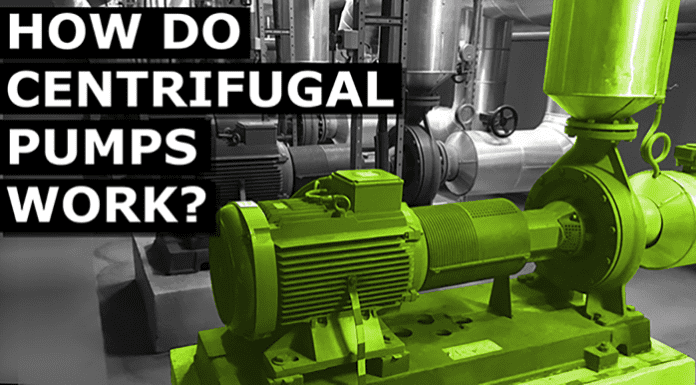
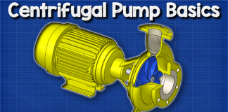
Centrifugal pumps come in many shapes, colours and sizes but they typically look something like this. The pumps consist of two main parts. The pump and the motor.
The motor is an electrical induction motor which allows us to convert electrical energy into mechanical energy. This mechanical energy is used to drive the pump and move the water. The pump pulls water through the inlet and pushes it out through the outlet. As we take the unit apart, we can see that we have a fan and a protective casing mounted at the back of the electrical motor. Then inside the motor we have the stator. The stator holds the copper coils and we’re going to look in detail at that a little later in the article. Concentric to this we have the rotor and shaft. The rotor rotates and as it rotates so does the shaft. The shaft runs the entire length from the motor and into the pump. This then connects into the impellor. Some models of centrifugal pumps like this one will have a separate shaft for the pump and the motor. Separated shafts are joined using a connection known as a coupling. Coupled pumps will usually have a bearing house which as the name suggests houses the bearings. The shaft continues into the pump casing as it enters the casing it passes through a gland, packing and the stuffing box which combine to form a seal. The shaft then connects onto the impeller. The impeller imparts centrifugal force onto the fluid which enables us to move liquids such as water through a pipe. The impeller is enclosed within the pump casing. The casing contains and directs the flow of water as the impeller pulls it in and pushes it out. Therefore we have a suction in that and a discharge outlet.
How Does a Centrifugal Pump Work?
At the back of the electrical motor, we see that the fan is connected to the shaft. When the motor rotates the shaft, then fan will therefore also rotate. The fan is used to cool down the electrical motor and it will blow ambient air over the casing to dissipate the unwanted heat. If the motor becomes too hot, the insulation on the coils inside the motor will melt causing the motor to short circuit and destroy itself. The fines on the outside perimeter of the casing increase the surface area of the casing which allows us to remove more unwanted heat. The electrical motor comes in either three-phase or single phase configuration depending on the application.
The rotor is connected to the shaft and the shaft runs from the fan through the rotor all the way up to the impeller. This way when the rotor rotates so will the impeller so now by creating the rotating magnetic field within the motor we spin the rotor which spins the shaft and this spins the impeller. Looking at the pump cashing we find a channel for water to flow along which is called the volute. This volute spirals around the perimeter of the casing up to the pump outlet. This channel increases in diameter as it makes its way to the outlet. The shaft passes through the seals and into the pump casing where it connects to the impeller. There are many types of impeller but most will have these backward curved veins which will either be open, semi-open or closed with some shrouds. These backward curved veins do not push the water. The curves rotate with the outer edge moving in the direction of the expanding volute. These veins will provide the fluid with a smooth path for the water to flow. We’ll see that a little later in the article. The impeller is submerged in water. When the impeller rotates; the water within the impeller also rotates. As the water rotates, the liquid is radially pushed out in all directions to the edge of the impeller and into the loop. As the water moves outwards off the impeller, it creates a region of low pressure which pulls more water in through the suction inlet. The water enters into the eye of the impeller and is trapped there between the blades.
As the impeller rotates, it imparts kinetic energy or velocity onto the water. By the time the water reaches the edge of the impeller it has reached a very high velocity. This high speed water flows off the impeller and into the balloon where it hits the wall of the pump casing. This impact coverts the velocity into potential energy or pressure. More water follows behind this and so a flow develops. The volute channel has an expanding diameter as it spirals around the circumference of the pump casing. As it expands the velocity of the water will decrease resulting in pressure increasing. This expanding channel therefore allows more water to keep joining and converting into pressure so the discharge outlet is therefore a higher pressure than the suction inlet. The high pressure of the discharge allows us to force the fluid through pipes and into a storage tank or around a pipe system. The thickness of the impeller and the rotational speed affects the volume flow rate from the pump. But the diameter of the impeller and the rotational speed would increase the pressure it can produce.
Centrifugal pumps are represented in engineering drawings with symbols like these. They can vary slightly from this so do check the drawing information section.

