Scroll to the bottom to watch the YouTube tutorial.

This is a three phase transformer. It has a delta primary and a wye secondary and its rated for 2kVA, confused? Don’t worry I’ll explain all of that.

The transformer basically just takes one AC voltage and coverts it into another voltage, we can get one, two or even three different voltages out of the secondary side, but there are no moving parts inside and there are no wires connecting from one side to the other.

You’ve likely seen these big green boxes at the side of the road. Inside is a three-phase transformer. These supply power to commercial buildings because they have a lot of lighting and equipment inside. Your home has much less stuff, so you only get a single phase transformer. It might be pole mounted or pad mounted.
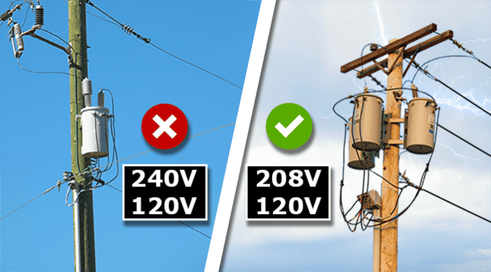
We can see three wires going to the home, but this is not three phase transformers. They typically connect to just a single phase and the neutral of the distribution grid, and it reduces this voltage to a much safer level.
Inside we basically have a primary coil, which connects across the phase and neutral. Then we have another completely separate coil, called the secondary, the two hot wires connect to the coil ends and the neutral connects to the centre. These wires run into the property to the electrical panel.
The primary side has a single-phase AC supply. The secondary side is also a single phase, between the two hot wires, giving us 240 volts, the current and voltage are flowing forwards and backwards between these two as it is alternating current.

But if we connect from the neutral to one of the hot bus bars, we get 120 volt, because we’re using just half of the secondary coil. The other side is also providing 120 volts, and uses the other half of the coil. If we plug an oscilloscope into the outlet, we would see a sine wave, with a positive and negative half of the AC sinewave. If we connect to each bus bar and the neutral, we see when one side is positive 120v, while the other side is negative 120 volts. The difference between these gives us 240 volts. So, it is just a single phase that is split into two.
However, you’ll often see banks of two or three transformers which do provide three phase power to commercial buildings.
But, where do these three phases even come from?
Well the power station generates three phase AC electricity. The generator basically just spins a magnet past a coil of wire, the magnetic field pushes and pulls the electrons in the coil forwards and backwards as the strongest part of the north and south pole passes through the coil. This creates the sine wave with a positive half and a negative half. This, is a single phase.
The generator spins the magnet fast enough that the sine wave repeats 60 times per second, and that gives us 60 Herts frequency. But, notice the output power is not constant with single phase.
We could add another coil which adds another phase and helps to improve this. Or we can add a third coil giving us three phases, and we see a much better, constant output power. Notice we have 3 phases, but 6 wires.
Also notice the current is always flowing forwards in one coil and backwards in another, so we can combine the coils and the current will share the wires, only using them when they need to.
We could try sending this power directly to the property, but it’s very far away, so the resistance of the wire means we will lose a lot of power just trying to get it there. However, if we increase the voltage, we can send the same amount of power with less current, so we lose almost nothing.
The power station feeds into a step-up transformer, this increases the voltage to hundreds of thousands of volts, and this will keep the current low over the long distance. Then when it reaches the city it enters a substation and the voltage is reduced in a step-down transformer. This continues on the sub transmission lines and might feed some larger industrial or commercial sites with their own dedicated substations. But it otherwise continues to the distribution substation where the voltage is again reduced and then distributed out along the streets to the properties.
Homes will then connect to one of the phases. While commercial properties will connect to all three phases.
Three phase transformers come in many designs, but inside, we basically just have 3 single phase transformers joined together. A transformer is simply two separate coils of wire placed around a steel core.
When current flows through a wire, it produces an electromagnetic field around the wire. When the current changes direction the magnetic field also changes direction. When we wrap the wire into a coil, the magnetic field joins together and forms a larger, stronger magnetic field.
When AC current passes through the coil, the magnetic field will increase and decrease, as well as change polarity as the current alternates direction. If we place another coil in close proximity, the magnetic field will interact with the electrons in the second coil and the magnetic field induces a voltage into that coil. If the path is complete on the secondary side, then a current will also flow.
However, a lot of the magnetic field is currently being wasted, so we use a steel core to concentrate and direct the magnetic field, making it stronger and more efficient.
The magnetic field will move around the core, this will induce an Eddy current within the core material. This wastes energy and generates heat, we don’t want that. So, we use lots of thin laminated steel sheets to build the core. Which helps keep the eddy currents as small as possible.
Now, when we apply a voltage to the primary side, we get a voltage on the secondary output side. The frequency remains the same.
If both coils have the same number of turns then the output voltage and current is the same as the input voltage.
If the secondary side has fewer turns than the primary, we get a lower output voltage but a higher current. This is a step-down transformer.
If the secondary side has more turns than the primary, then we get a higher output voltage but lower current. This is a step-up transformer.
In each case, the power transferred is the same value.

For example, If this step-down transformer was supplying 200Volts and 10Amps to the load. Then we have 2,000 volt-amperes on the secondary side. The primary side would see 5Amps and 400Volts, which is also 2,000VoltAmperes or 2kVA. So the power transferred is the same, but the voltage and current change.
Now we could have three separate transformers, but to save costs, materials and space we often combine them. The three coils on the primary are connected to the phases in either delta or wye configuration. The secondary side coils can also be delta or wye. So we can have a delta – delta, wye – wye, a wye – delta or delta – wye transformer.
The name plate on the side of the transformer will tell you how it is configured.
For wye configuration, we connect one end of each coil together, the other end connects to a phase. Notice it looks like the letter Y, so it’s easy to remember. From the central point of the coils, we can connect a neutral wire and also a ground connection. This allows us to connect to single phase, or all three phases.
We can see with this transformer, that one side of each coil connects to a dedicated terminal for each phase, but the other end of each coil connects into the same point, using 4 terminals. So we know this is a wye connection.
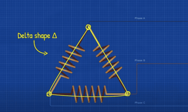
With the delta, all the coils are connected end to end, with the phases connecting between the coils. This forms a triangle that looks like the Greek symbol for delta. There isn’t a neutral with this design, so it’s only for 3 phase loads. However, there are some variations like the high leg and open delta, but I’ll explain those later in the article.
With this transformer we can see each coil connects to a terminal, but the other end of each coil connects to a different terminal. So, we know this is a delta connection.
The coils could be on either side of the core, but we usually find them placed concentrically with one surrounding the other.
So maybe we have a pad mounted transformer powering a small commercial building. The stickers and name plate tell us it’s a 12,470V Delta primary, and a 208/120Volt Wye secondary, and the transformer is rated for 150kVA. So we have 3 phases and 3 wires entering the transformers primary side with 12,470Volts between each phase. The secondary side is wye connected with 4 wires leaving the transformer. It’s a step down transformer with 208Volts between any two phases, or 120V between any phase and the neutral. It can handle up to 150 thousand Volt-Amperes in total, so that’s 50 thousand per phase or per coil set. Which means we can supply up to 416Amps on each phase and through each coil on the secondary. and that would cause 4 Amps to flow through the primary coils and that causes 6.94 Amps to flow through each line. That is our maximum limit of the transformer, the actual kVA transferred depends on how much equipment you connect and power. We just can’t exceed the transformers limit otherwise it’ll overheat, cause a short circuit and it will simply burn out.
Our next example is this larger building might need to power 480V three phase motors, 277Volt fluorescent lighting, 208Volt appliances and 120Volt outlets.

Outside the building, we find a pad mounted transformer rated 12,470 GY/ 7200 and that is on the Primary side, and on the secondary side we have 480 volts/277 volts, and the transformer is rated for 500kVA, and this supplying the building. We know it’s a Wye Wye transformer, with 4 wires entering the primary side and 4 wires leaving and entering the building. It also tells us the primary side is grounded.
So there’s 12,470 Volts from line to line or 7,200Volts from line to neutral on the primary side. And there’s 480Volts line to line or 277 Volts line to neutral on the secondary side. Now this might enter the building and connect into a switchboard, from here it might feed a panel which feeds a motor 480Volt three phase. And maybe it feeds a panel which supplies a smaller step down dry type transformer and that transformer feeds a 208/120Volt panel.
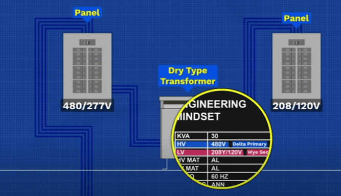
This smaller transformer is a 480 Volt delta primary, and 208 volt/120Volt wye secondary and the transformer is rated for up to 30kVA. This provides 208Volt three phase or 120Volt phase to neutral.
Inside this transformer we have the three coils and the terminals labelled H1, H2 and H3. This is our high voltage side where the phases connect for the delta connection. Then we have X1, X2 and X3 along the bottom, this provides our three output phases, there is also an X0 terminal for the neutral.
Notice on the coil these black jump leads and the 7 connection points on each phase. These are called taps. We can move the jump leads to increase or decrease the length of the coil.
Lets say we have 84 turns on the primary with 5 taps and 20 turns on the secondary. We measure the supply side and have 480Volts, so the data sheet says to use tap 3 on all phases, which has 80 turns, and provides the designed 120Volt output.

However, if we measured 504Volts on the supply, we would get 126Volts on the secondary. So, we need to increase the coil and use tap 1 with 84 turns to reduce the output voltage back to 120Volts.
But if we had only 456Volts on the primary, then we’d need to use tap 5 with 76 turns to get the 120Volt output.
So we can compensate for supply voltage variations using the taps. We usually find the primary coil on the outside because we can easily change the connections.
The large pad mounted transformers also have tap changers, but the coils are submerged in oil for cooling so we can’t access them. The coil connects to different points on the tap changer and the dial changes which parts of the coil are connected across.
We often find smaller commercial buildings supplied by 3 pole mounted transformers connected in delta wye, this provides three phase 208Volts or single phase 120Volts. Or it could be 480Volts and 277Volts.

Sometimes they are connected delta – delta, usually providing 480Volt three phase only.
Sometimes only two transformers are used, forming an open delta. It typically provides 240Volt three phase and 120Volt single phase. With a high leg 208Volts. However, this design is missing a coil so it has a reduced capacity. I’ll explain why in just a moment.
I’ve made these 3 phase transformer mugs with the formulas and diagrams on to make it very easy to remember. And you can grab my PDF sheet too. Links down below for that if you’d like one.
For Wye connections, we have all three coils joined at the centre. At this point we normally ground the transformer, and we run a neutral wire from here. So we have a 3 phase 4 wire system. This gives us our line voltage or line to line voltage and also our phase voltage, which is often called the line to neutral voltage.
In this example we have a 208/120 volt secondary, so we have 208Volts between any two lines. Or we have 120Volts between any line and the neutral. Now It’s the coil that’s producing the 120V, and that just depends on how many turns the coil has and the primary applied voltage.
The simple reason we get 208Volts is because we are connecting across two coils but these coils are not in phase. One is in the positive while the other is in the negative cycle. At the widest point, roughly 120 degrees rotation, phase A will be 104Volts rms, while phase C will be negative 104Volt rms. So the difference is 208Volts.

Or we can solve using trigonometry, we have three coils which are all 120Volts, and they are 120 degrees rotation apart. So, all we need to know is the length of the side of the triangle.
From trigonometry we use this formula and drop in our values and that gives us 208Volts between two phases.
Now no one wants to write that out every time, but notice the ratio between the two voltages, it’s around 1.732 etc etc etc… and this number just goes on and on, so engineers just say 1.732 or they use the square root of 3 because it’s even easier. We get that because if we square the ratio meaning we just multiply it by itself, then we get 3. So to undo that to find the original or root number that was used to make this square number, we take the square root. So, the square root of 3 is 1.732 etc.
So, if we know the phase voltage, we multiply this by the square root of 3 to find the line voltage. If we know the line voltage then we divide by the square root of 3 to find the phase voltage.
Luckily the current in wye configuration is super easy. The phase current is the same as the line current. So if we had 100 amps on the line, we would also read 100 amps through the coil.
In the delta connection, each coil is joined end to end. The phase wires connect at the intersections between two coils. This gives us a 3 phase, 3 wire system. There is no neutral, so we only have Line voltages. In this example we have 480Volts between any two phases.
The line voltage is the same as the voltage across the coil or the phase voltage, because we only have 1 coil between any two phases.

But the current is split between two coils, and we know they flowing at different times. So the line current will be larger than the phase current. If we know there’s 43.3A flowing on the line, then we divide this by the square root of 3 to get 25Amp on the coil. And if we know the coil current is 25Amps then we multiply by the square root of 3 to get 43.3Amps on the line . A fairly quick way to mathematically see that is to simply draw each of our coil currents 120 degrees apart. To find line A current, we have coil C to A and coil A to B connected to it.
So we reverse coil C to A, which would sit 60 degrees apart from the other two coil currents.
Then we slide that line to the end of the A-B coil current line- and really, we’re just making a parallelogram, but we are going to skip that step. We know this angle must be 180 degrees total, so 180 degrees minus the 60 degrees we already have, means this remaining angle is 120 degrees.
So our line current will be the resultant line between these two points. So now we just have a triangle with an unknown side, so we can use our trigonometry to solve that. So our line current is 43.3Amps. Which is 1.732 times larger than the coil current. Which is equivalent to the square root of 3.
So if we have a delta Wye transformer, with 80 turns on the primary and 20 on the secondary, we have a ratio of 4:1. The primary side has 480Volts between two phases, so there’s 480Volts on the coil. We calculate the voltage in our secondary coils as therefore 120Volts. That’s our phase voltage, so we can easily find the line voltage of 208Volts.
The secondary side has 100Amps on each phase. We find the primary winding current of 25A through each coil. The current on each line is therefore 43.3Amps
So the primary side power is 36,000 volt-amperes.
The secondary side is also 36,000 volt-amperes.
So the power transferred is the same but the voltages and currents are transformed.

In the high leg delta, we have three coils connected in delta. In this case the voltage between any two phases is 240V. The voltage across the coils is also 240Volts. But, one of the coils has a wire connected to the centre of the coil, this is also grounded. The wire acts as a neutral so we can use half the 240Volt coil to get 120Volts between phase A and neutral or phase C and neutral.
But, between phase B and neutral we get 208Volts because we are using one and a half coils. We can find that using trigonometry.
This is why the B phase will usually be orange in the panel to warn it’s a higher voltage, and that’s because it’ll likely destroy any 120volt appliance if its improperly connected. The open delta uses just two transformer coils, so it’s missing one of the coils. We get the same voltages in the coils, so it’s the same voltage between lines and same voltage between line and neutral, however the capacity is reduced.
If we had three transformers, each rated 20kVA, that gives us 60kVA in total. Then the maximum coil current or phase current would be 83.33Amps. The line current is therefore 144.33Amps.
But, with only 2 coils, the maximum line current is equal to the maximum phase current.
So, our total capacity is now just 34.6kVA. That’s 57.7% in comparison, or a reduction of 42.3% compared to the 3 transformer delta.
Our rated capacity for this two transformer design is now just 40kVA but we can only handle 34.6kVA, meaning we can only use 86.6% of the stated capacity. So this design is cheaper to install but not always practical, but it’s easy to increase at a later date.

