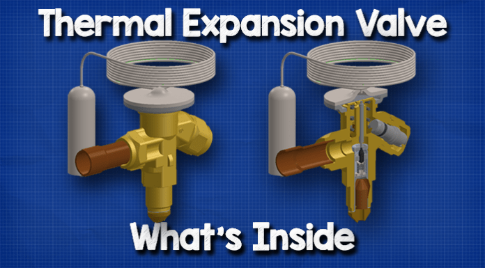
Whats inside a thermal expansion valve and how the thermostatic expansion valve or TXV works in a HVAC refrigeration system. Learn the basic working principles that allow the thermal expansion valve to meter the flow of refrigerant into the evaporator of chillers and air conditioning units.
Scroll to the bottom to watch the YouTube video
If you want to get the most out of any Thermostatic Expansion Valve, then you should definitely check out TXV Superheat Tuner. It’s a free mobile app available from Danfoss. You can use it to optimize the energy efficiency of a cooling system in just 15 minutes and save money on energy costs.
🏆 Download TXV Superheat Tuner for free – http://bit.ly/GetTXVsuperheattuner
Where do we find the expansion valve
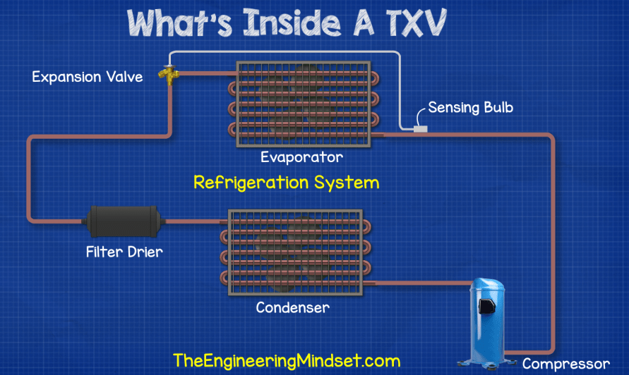
Expansion valves sit between the condenser and the evaporator in a refrigeration cycle.
In this model which is a T2 thermal expansion valve. We have the main body which is made from brass. On the body we have the refrigerant inlet at the bottom of the valve. Then the refrigerant outlet at the side and on the other side we have a cap which can be removed. Under that is a screw which is used to manually adjust the superheat, we’ll see how that works later on.
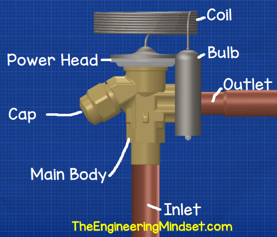
On the top we have this large head called the power head, a coil of very thin tubing known as the capillary tube and there is a large bulb at the end known as the sensing bulb, these are all made from stainless steel.
The coil is stretched out and the bulb sits at the exit of the evaporator to sense the superheat.
We have previously covered, in great detail, how thermal expansion valves and electronic expansion valves work as well as the different types of expansion valves used in chillers.
What are thermal expansion valves used for
Expansion valves control the flow of refrigerant into the evaporator in response to the cooling load. It measures the superheat at the outlet and reacts to this, increasing or decreasing the amount of refrigerant flowing into the evaporator to try and maintain a constant superheat. This also ensures that the refrigerant is boiling off and leaving the evaporator as a slightly superheated vapour and prevents liquid refrigerant entering the compressor. Liquids can’t be compressed so if it enters the compressors it can cause severe damage and even destroy it.
The bulb is filled with a refrigerant which is kept completely separate to the refrigerant in the rest of the system, these two refrigerants never meet or mix they’re always separated.
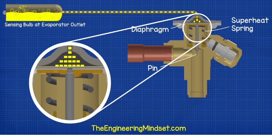
The superheat boils the refrigerant inside the bulb and as it boils it creates pressure. The pressure travels along the hollow capillary tube and into the power head. The power head controls the flow of refrigerant and we’ll see inside that later.
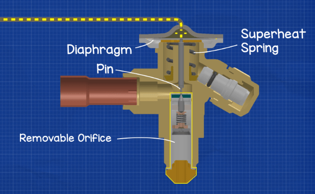
We place a removable cartridge inside the inlet of the expansion valve. This has an orifice which works with the valve to control the flow of refrigerant. There are different sized ones depending on the cooling capacity and refrigerant being used.
I’ll just put the valve into a bench vice to keep it steady, while I cut it open.
Because of the delicate parts inside, I used a hacksaw to cut this one open. It takes a long time but the angle grinder could rip apart the internals and I want to be able to show you these parts.
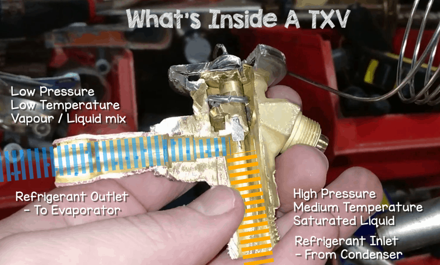
We have the main body which holds everything together.
We have the refrigerant inlet coming in from the bottom of the main body, in this vertical pipe. Then we have the refrigerant outlet in the horizontal pipe. So the refrigerant comes from the condenser and enters the valve body via the inlet as a high pressure, medium temperature saturated liquid. It then passes through the valve body and when it leaves, it exits the valve through the outlet and will now be a low pressure, low temperature liquid / vapour mixture.
So what’s causing the change in pressure, temperature, phase and also controlling the flow of refrigerant. Well we can see this small pin here.
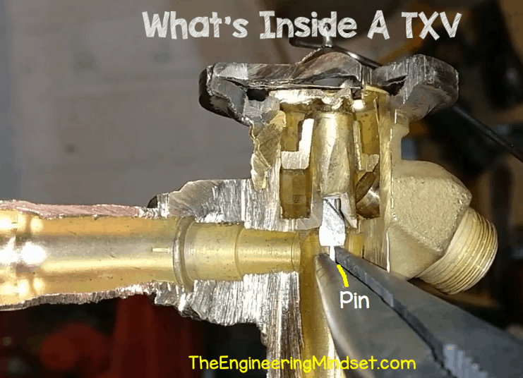
This is connected to the diaphragm up in the power head. The diaphragm is a thin sheet of flexible metal. As the diaphragm moves up and down it causes the pin to move up and down. Underneath the diaphragm we have a spring which is pushing against the diaphragm, we can use this to adjust the superheat and we’ll look at that a little later in the video.
Above the diaphragm we have this empty chamber which is connected to the capillary tube and then to the sensing bulb. The chamber, capillary tube and bulb are all hollow.

I’ll just cut through the sensing bulb using an angle grinder to show you the inside, as you can see it’s just an empty cylinder which is usually filled with some refrigerant. The refrigerant in the bulb and capillary is completely separated from the main refrigerant which flows in the system, this isolated refrigerant only moves between the bulb, capillary tube and the top of the diaphragm.
The sensing bulb sits at the outlet of the evaporator. As the cooling load on the evaporator increases the superheat increases at the evaporator outlet. Because the sensing bulb is in direct contact with the pipe at the evaporator outlet, the thermal energy transfers and causes the refrigerant inside the sensing bulb to expand and boil. Because the sensing bulb, capillary tube and the chamber are all hollow and are a sealed system. As the refrigerant expands and boils, it causes the pressure inside to increase. This pressure travels along the capillary tube and makes its way to the chamber above the diaphragm. As the pressure increases it pushes down on the diaphragm and that pushes down on the pin. The pin controls how much refrigerant can flow, but to do that we need one more part.
Inside the inlet of the valve we place an orifice assembly. These are replaceable and come in different sizes to suit the cooling capacity and refrigerant used. Inside is a small strainer which protects the valve from blockages, and then there’s a small orifice, or hole, which is blocked by a spring loaded stopper. Our pin, in the main valve, pushes down on this stopper to open the valve. The further the stopper in pushed down the more refrigerant can flow.
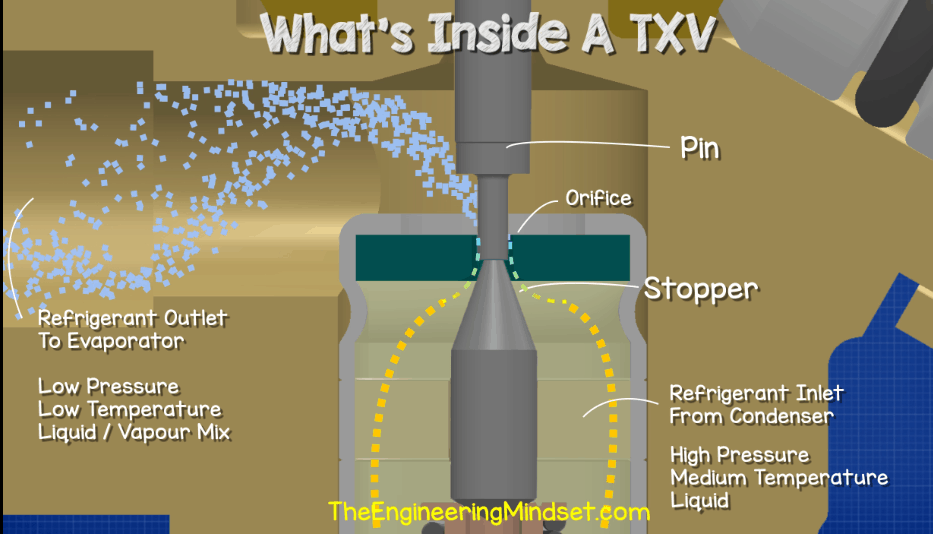
As the cooling load increases on the evaporator, the superheat increases at the outlet. The sensing bulb at the outlet detects this and the refrigerant inside boils causing an increase in pressure along the capillary tube.
This pressure pushes the diaphragm down and that pushes the pin down which opens the valve and lets more refrigerant flow. As more refrigerant flows, the superheat decreases and so the pressure in the sensing bulb and capillary tube decreases which means there’s less pressure pushing the diaphragm down. The spring then pushes the diaphragm back up, that causes the pin to move up and as the pin rises the spring loaded stopper begins to close the orifice which reduces the amount of refrigerant that can flow. This repeats constantly and stabilises the valve to ensure the correct amount of refrigerant can flow.

We mentioned earlier about adjusting the superheat control. Well this plug on the side is threaded internally and if we rotate this it will move the slider up or down depending on which way you rotate it. As the slider moves up and down it changes how much force the spring is applying to the underside of the diaphragm which changes the sensitivity of the device and allows you to therefor tune the expansion valve and adjust the superheat.

