Scroll to the bottom to watch the YouTube tutorial.

Will this circuit breaker save you from an electric shock? NO. Will any of these? No! Why?

Well this number here tells us the breaker is rated for 3 amperes of current. It’s one of the smallest you can buy.

For reference, this lamp is around 0.14 amps, this toaster is around 3 amps and this hair drier is 7.8 amps.
Your body has a very high resistance, we can touch a low voltage battery and nothing really happens. But the cables in our homes carry much higher voltages, touch those and current can flow straight through you.
At just 20 milliamps, your muscles contract and you probably won’t be able to let go. At 0.2 amps, for 1 second, and your heart stop the heart beating. So this 3 amp breaker isn’t going to trip and save you. It will just provide power to whatever is connected to it, including you.
In fact, even this 3 amp toaster won’t trip this 3 amp breaker. This letter tells us that and I’ll explain that later in the article.
So if it doesn’t protect people, then what does it protect?
It protects cables and property, and property is expensive. Why property?
Well the current flow through cables in our properties. Inside the cable is a metal conductor which provides a low resistance path to the electrical load. This is covered with insulation to protect us and prevent the current from taking any alternative routes.

Whenever current flows through a wire, it generates heat. Now, this isn’t a problem but as the current increases then the temperature increases and at a certain point the insulation weakens and eventually melts, exposing the metal conductor and even causing fires.
Each size cable is rated for a certain maximum current, so the breaker must not exceed that value.
The breaker will detect excessive current and automatically trip to protect the cable. It does that using these internal parts, which I will explain in just a moment.
If we pass 20 amps through this 10 amp breaker, how long will it take to trip? Tell me in the comments section and I’ll give you the answer at the end of the article.
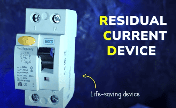
To protect people, we use another device which measures the current flowing into and out of the device, it then trips if these two values are not equal. But that’s a topic for another article.
This circuit breaker only detects short circuits and overloads.
Ordinarily the current flows from the line, through the load, and back on the neutral. This is AC current so it actually flows forwards and backwards, but I’ll explain as DC for simplicity. The resistance of the load limits the current. But if the line and neutral come into direct contact we have a short circuit, because there’s no resistance, so a huge and instant surge of current occurs and trips the breaker instantly.
We know that the breaker is rated for a certain current. Each time we plug an appliance in, we increase the current. Eventually we will exceed the breaker limit and it will trip. This is an overload and it takes a lot longer to trip.
We can manually operate the breaker to isolate the power, but it will trip automatically, once the fault is removed we can manually reset the device. Even if the lever is held in the on position, most will still be able to trip, thanks to a clever design.
Most of the world uses these MCB’s for residential uses, but north America and a few other places use plug-in breakers, although MCB’s are still often used in industrial and controls applications in those regions.

Each manufacturer has a slightly different design. They all work in a similar way, but you shouldn’t mix them.
This is a consumer unit, installed in the UK. We can see it has lots of MCB’s.
Remember electricity is dangerous and can be fatal, you must be qualified and competent to carry out any electrical work.
Inside the consumer unit, we have the live and neutral incoming supply, this enters a double pole main switch, the live passes through to the RCD and then a metal bus bar that connects into the bottom of the RCD. This will provide power to multiple circuit breakers. A wire runs out the top of the breaker, off to the load. A neutral wire then runs from the load, and back to another neutral block. This block connects to the RCD. The RCD connects to the main neutral block and this connects to the main switch. So, current flows in on the live, through the main switch, into the RCD, through the circuit breaker, through the load and into a terminal block, then back to the RCD, to the main terminal and out through the main switch to complete the circuit. Although as this is AC electricity, the current actually flows back and forth.
Looking at the circuit breaker, we find a notch at the back, which lets us clip onto a DIN rail. This rail is not electrified.
On the front we have the lever which flips up and down and indicates the status. There’s usually a indicator window too.
There’s lots of text which I’ll explain later in the article. We also find two screw terminals. These let us adjust the terminals to grip a wire or bus bar on the top and bottom. Be careful though as it can go behind, giving a false connection and you definitely don’t want that.
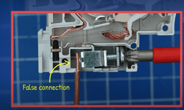
There’s often a heat vent on the top, and on the bottom, we see a tiny hidden screw. I’ll explain that in just a moment.
I had to drill the rivets, but, we can then remove the case to see all the strange parts inside. Each manufacturer has a slightly different design but they all work in a very similar way.
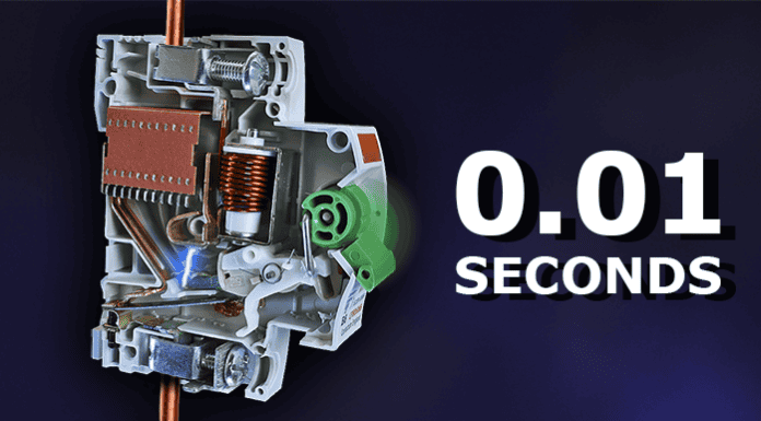
We basically have a bi-metallic strip for overload protection, a solenoid for short circuit protection, a lever, a mechanism with movable contact, an arc chamber as well as two terminals.
In normal operation, the current flows through the bottom terminal, along the track, through the bimetallic strip, through the braided wire to the movable contact arm, through the contact pad, into the copper track, then into the wire and around the solenoid coil, then out the wire and through the top terminal. And it then goes off to the load. The contact arm simply moves away to break the circuit.
To understand how it works, we start with the main lever and notice it is spring loaded. A small spring pushes against the case and forces the lever into the off position.
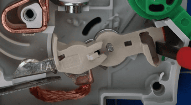
Next, we see the mechanism which has 3 main parts. At the centre is the main arm which is held in position with a pin, the arm can pivot around this point. A metal contact plate is attached to this arm, when the arm moves the plate also moves. A spring is attached to this arm and pushes against the case, forcing the arm downwards. A trigger arm sits on top of the main arm and can move a small amount around the same pivot point. The trigger arm has a small opening at the end which aligns with a channel in the main arm. A small spring pushes against the trigger arm and main arm, forcing the trigger arm to rotate and close this gap.
A metal link is inserted into this gap and connects to a hole in the lever. The main arm and trigger arm partly surround the metal link. When we rotate the lever, the metal link will also move and follow the rotation of the lever. This pushes down on the main arm causing it to also rotate which compresses the spring. The lever is prevented from going any further by the case.
The spring of the main arm is now pushing firmly against the metal link. The tension of the spring on the trigger arm is just enough to keep the link in place. But, if a small downward force acts on the trigger arm, it will move and release the metal link. The spring of the main arm instantly forces the arm downward into the off position.
This happens so fast, we need to see it in slow motion. You can see the trigger arm moves which releases the metal link, the main arm spring instantly moves the arm, opening the circuit.
The bi-metalic strip and the solenoid can both trigger the arm and trip the breaker.
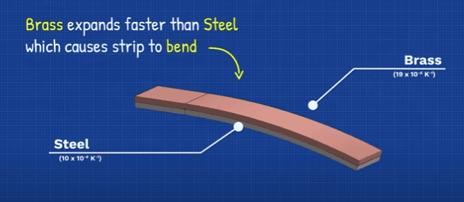
The bi-metallic strip protects from overloads. This is made from two different metals joined together, each with a different thermal expansion coefficient.
In this version you can see the different colours of the materials. There are other designs, it depends on the manufacturer.
When the strip is heated, one metal expands slowly, the other expands much faster which causes the strip to bend.
Current flows through the bi-metallic strip which generates heat and causes the strip to bend. The braided cable allows some flexibility. But, if too much current flows, the strip will push the trigger arm and trip the breaker.
There is also a small screw here, this is used by the manufacturer to ensure the strip bends at the designed level of current flow. You should not make adjustments yourself.
The next part is the solenoid, which protects from short circuits. This is simply a coil of wire connected across the upper terminal and a copper track. It is held in position by a metallic support and the moulding of the case. Inside the coil is a plastic case with a spring-loaded piston inside. The spring pulls the plunger upwards, but we can easily move this.
The full circuit current will pass through the coil in normal operation but the piston won’t move. However, if a short circuit occurs, the piston will be immediately pulled down until it hits the trigger arm which activates the mechanism and cuts the power.
Let’s see that in slow motion. You can see the piston gets pulled down and activates the mechanism.
Why does this happen?
When we pass current through a wire, it generates a magnetic field. If we reverse the current, the magnetic field reverses. We can see that by placing some compasses around the wire. The larger the current flowing through the coil, the stronger the magnetic field. If we wrap the wire into a coil, the magnetic fields join together making a stronger, larger magnetic field.
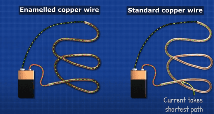
The wire is coated with an enamel insulation, so the current has to flow through the entire coil, otherwise it’ll take the shortest path and cause a short circuit.
Under normal conditions, a magnetic field is generated but it’s not enough to overcome the force of the spring. However, during a short circuit, there is very little resistance or impedance, so the current instantly increases to potentially thousands of amps. This will create a very strong magnetic field, which easily overcomes the spring force and pulls the piston in.
Our circuit uses alternating current so the current actually flows forwards and backwards. The piston will be pulled down, no matter the direction.
You can notice that this small 6 amp breaker has a thin wire coil with lots of turns to help increase the strength of the magnetic field, but these larger current rated breakers have much thicker wires, and fewer turns.
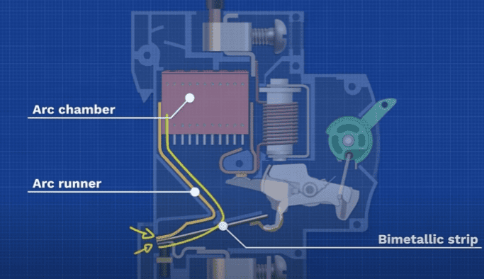
So, both the bi-metallic strip and the solenoid can trigger the mechanism and break the circuit. But when the contact point opens, we often find an arc forming, because a lot of energy was flowing.
This arc is an extremely high temperature and could melt through the case. So, we use an arc chamber.
This is simply multiple parallel metal sheets, usually steel or copper plated, which are held together by an insulating material. The plates are all electrically isolated from each other.
A copper track, called the arc runner, runs from the bi-metallic strip up along the side of the arc chamber. Sometime it is angled, sometimes it is curved. We usually find a small pad on the upper copper track to protect against the arc and improve the connection. Larger current devices typically have a double layer track.
When the contact arm opens, the arc forms between the fixed and moving contacts. The copper track widens the path leading the arc away. The arc is spread over a larger and larger distance to help weaken it.
A small arc will naturally break and dissipate as the path widens. But a larger arc will continue and hit the chamber. The plates will divide the arc into lots of smaller arcs which can’t sustain themselves and dissipate their energy. The arc chamber absorbs the heat and vents this out the top.
We often find extra insulation around the chamber to protect the case.
So why doesn’t this 3-amp breaker trip at 3 amps of current? Well the letter B means we need to look at the type B chart, which is provided by the manufacturer. Typically, we also find type C and D, and these have their own corresponding charts.
On the vertical axis, we have time and along the horizontal we have current. The curved section relates to the bimetallic strip for over current protection. The vertical section relates to the solenoid for short circuit protection.
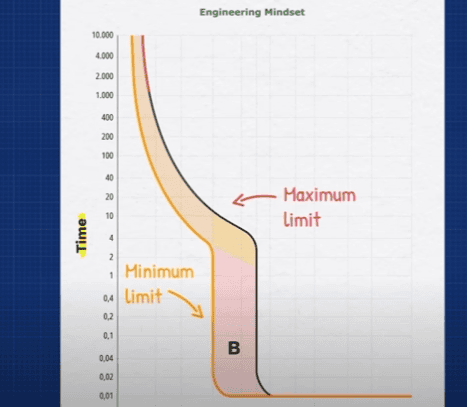
The two lines show the minimum and maximum limits. The breaker will trip within this zone.
Along the bottom we have multiples of the rated device current. For simplicity lets assume a 10-amp rated breaker.
So, we have 10 amps, 20 amps, 30 amps etc. If 20 amps passes through the breaker, that’s 2 times the rating, we draw a line up and see it hits the lower limit of the bi-metallic section, and this occurs at around 9 seconds. Then it hits the upper limit at around 50 seconds. So this should trip between 9 and 50 seconds, when 20 amps flows through the breaker. At 1 times the rating, so 10 amps, we see it doesn’t hit the line at all, therefore this breaker will not trip if 10 amps flows through it. It won’t trip until it hits 1.13 times the rated current, so 11.3 amps, and it’ll take 3,600 seconds which is 1 hour.
At 3 times the rating, so 30 amps, it will take between 0.02 seconds and 11.5 seconds to trip. That is the worst-case scenario.
If 60 amps flow, it’ll take 0.01 seconds to trip.
So, type B breakers will instantly trip if between 3 and 5 times the rated current flows through them, or anything above that, but they will take longer for anything less than that passes through it.
Type C and D take longer, hence the charts are extended. So, a type C won’t trip instantly unless 5 to 10 times the rated current flows through it, and type D won’t until 10 and 20 times the rated value.
Why would we want that?
Well, when an appliance is running, it has a fairly constant current. But, when we plug in or turn on an appliance, we have an inrush current because the capacitors and inductors inside are all storing energy, and this causes lots of current to flow. So, for a fraction of a second, we have a large current flowing, and then it will normalise.
We need different breakers for different applications and circuit, for example:
This induction motor might have a running current of 5 amp, but the inrush current is 4 times that at 20 amps and it only lasts 0.03 seconds, therefore, we couldn’t use a type b breaker as it will trip each time the motor turns on.

