How does three phase electricity work? In this article we’ll be explaining how three phase electricity works, we’ll start from the basics of a single phase alternating current generator and then add in a second and third phase to understand how three phase electricity works. We’ll also cover why and where three phase power is used as well as why we don’t use more phases. Scroll to the bottom to watch the video tutorial
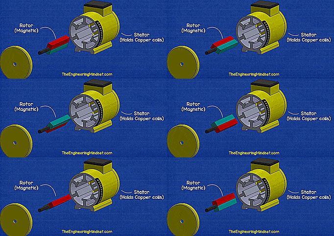
So first of all lets start with a simple AC generator, we’ll start with a single phase to understand whats happening and then add in the other phases until we get to three phases.
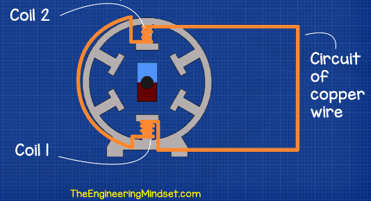
Let’s take a copper wire and wrap it into two coils then place these coils opposite each other, within a stator, and connect the ends together to create a complete circuit.
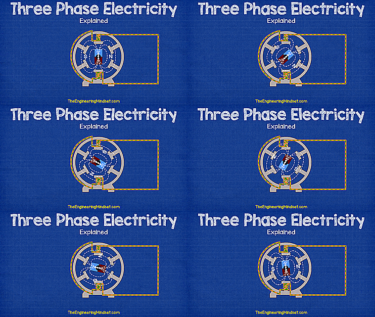
Now if we place a magnet in between these coils and we start to rotate the magnet, then the magnetic field will disturb the free electrons within the copper wire and an electrical current will begin to flow. We’ve covered how the free electrons flow in our previous article on electricity basics so please check that out if you’ve not already done so. click here to view the video and article on how electricity works.
As the magnet rotates so does the polarity of the magnetic field. As you can see in the illustration the north and south pole are rotating and as they rotate they pass across the coils which will force the electrons to move.
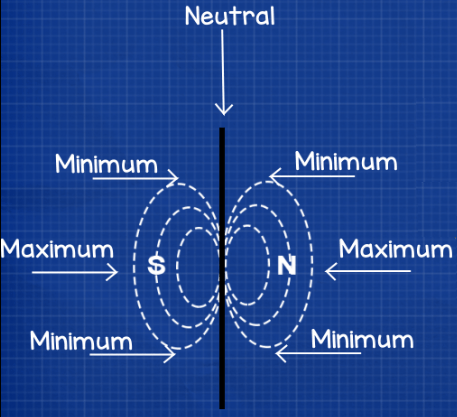
Notice the lines of the magnetic field are in these oval shapes on each side and they meet through the central axis of the magnet. You can think of one side at being positive and the other side being negative and between these ovals the magnetic field is neutral. You can see that the intensity of the magnetic field increases on either side up until the centre where it is at its maximum strength and then it decreases again until it gets back to the neutral point.
As the magnetic field rotates through the coil, the coil will experience the increasing intensity of the magnetic fields positive half. During this increasing intensity the free electrons, within the copper coil, will be pushed and begin to move faster and faster in one direction up until it reaches the maximum point of the magnetic field, then as the magnetic field decreases the flow of electrons will begin to slow all the way until it reaches the neutral point where no electrons will flow. Then comes the negative side of the magnetic field, as this passes through its going to pull the free electrons backwards. Again the flow of electrons will flow faster and faster up until the maximum point of the magnetic field and then it will decrease back to the neutral point.
This is why AC electricity is called alternating current because the current of electrons alternates in direction backwards and forwards just like the tide of the sea.
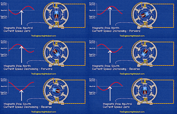
If we were to plot on a graph the speed of the electrons flowing during the rotation, then we get a sine wave pattern. In this sine wave you can see the electrons are stationary at start, in the neutral zone, and then the speed increases through the positive half to the maximum. It then decreases all the way to neutral where no electrons flow again and then comes the negative half where the electrons speed up to the maximum point, and then slow down until the magnet has completed 1 full rotation where this will repeat.

This complete rotation is known as a cycle and the number of cycles per second is called frequency which is measured in hertz. You’ve probably seen 50Hz or 60Hz written on your electrical goods, this means the generator of the power station is completing a full rotation either 50 or 60 times per second. The direction of the current is changing 50 or 60 times per second. When it’s written on electrical products this is just tell the user what type of electricity it should be connected to.
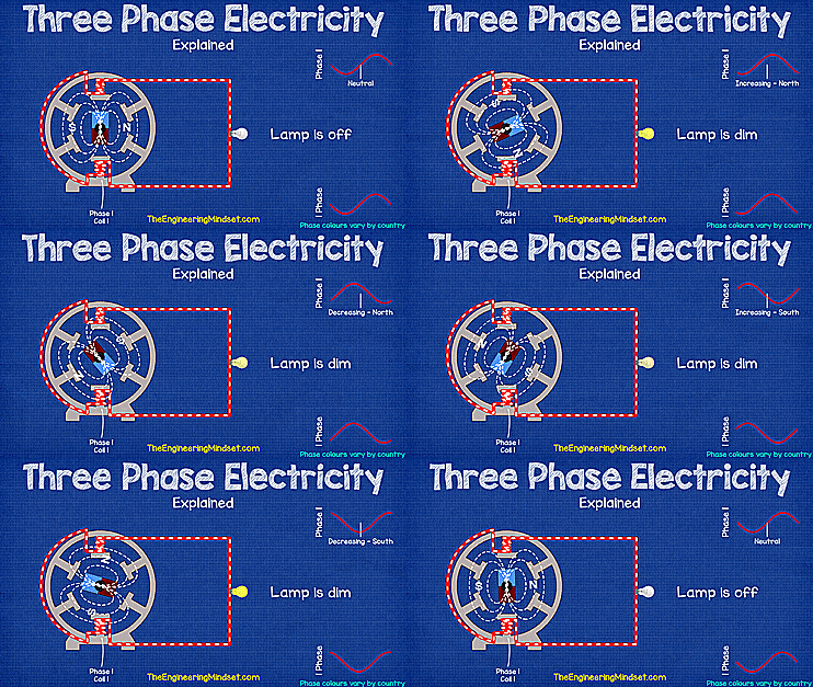
Now coming back to the sine wave we saw earlier. This plot of current also represents power, and if we connect a lamp into the circuit we see it will increase in brightness all the way to the peak then it decreases in brightness down until the neutral point where the lamp is off as no current is flowing, but then it increases in brightness again as the electrons start to flow back through it in the opposite direction until again it reaches the neutral point.
At the neutral point in the cycle the lamp is not producing any light, at the increasing and decreasing points in the cycle the lamp is dim. The lamp is only fully on and bright at the maximum points in the cycles. This means the light is flickering constantly on and off.
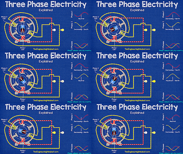
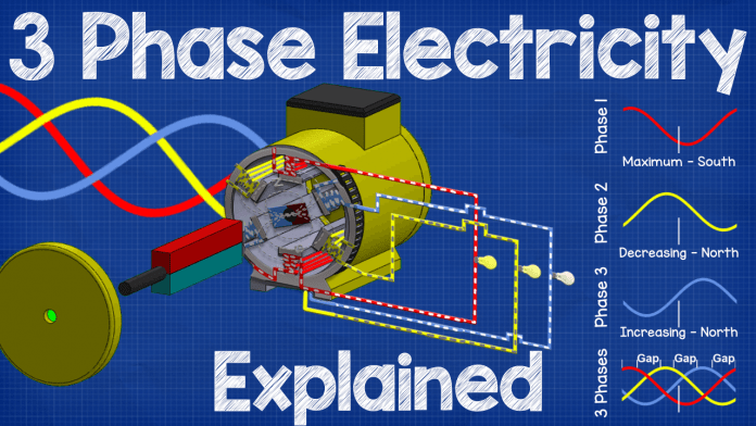
To improve this we can add in another set of coils, or a second phase, into the generator and place these 120 degrees rotation from the first set of coils, and then connect this up to another lamp. This rotation means the coils experience the changing intensity of the magnetic field at different points in time. The first coil reaches its maximum current and brightness and as it decreases the second coil will begin to increase.
This has improved the lighting but there’s still a gap which will cause a flicker so we can add in a third set of coils or a third phase and this will mean that one of the lamps are almost always at its maximum brightness so the lighting is nearly constant. This is the basics of three phase electricity. This means more power is delivered and a more consistent speed is achieved.
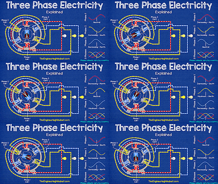
There are still some small gaps between the phases and you could keep adding in more and more phases to fill in these gaps but this becomes more and more expensive to keep running all these cables, so three phase electricity became widely accepted as it is a good compromise between power provided and cost to build.
In the real world you’re not going to use three lamps on different phases to create lighting. The lamps in your homes are all on single phase but they are flickering its just that they are turning on and off so fast that the human eye can’t see it unless you record the lamp in slow motion.
A more practical application is to power electrical induction motors and other commercial and industrial equipment as three phase will provide a lot of power to these items meaning you can pump water higher and run motors faster.
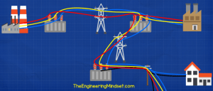
Power is generally generated and distributed in three phase and transformers are used to change the voltage, if you want to learn how transformers work we’ve also covered that too, links are in the video description below.
Now one of the interesting things with three phase power is that you can connect to all three phases and power large industrial equipment or you can also connect to only one of the phases and also power small electrical goods.
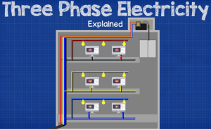
This is generally how large tower blocks and sky scrapers distribute electricity through the building. The lifts motors and air conditioning pumps need three phase power but the computers and office equipment will need single phase power. So they distribute three phase power up the building and then draw off from this as needed
The same occurs with the distribution of electricity across a city. Houses will be connected to only a single phase because they do not require much power, where as large buildings will be connected to three phases as they require a lot of power.




awesome
[…] in our last three phase tutorial we looked at the basics of whats happening inside three phase electricity systems and in this […]
I think you have your magnetic field lines drawn wrong in this tutorial, your north and south points are marked in the wrong position, also where you have the strongest and weakest points in the field seem to be marked wrong. Might be worth reviewing this.
I think you have your magnetic field lines drawn wrong in this tutorial, your north and south points are marked in the wrong position, also where you have the strongest and weakest points in the field seem to be marked wrong. Might be worth reviewing this.
The north -south regions of the magnet are 180 degrees away from each other, so the mid-point in BETWEEN them would be where the strongest magnetic field would exist.
The drawing is CORRECT.
For the life of me I cannot wrap my head around how the other phases can act as the return for each other.
[…] We have covered this in great detail previously, do check that out HERE. […]
Your video is very intuitive and vivid. Help a lot for first year electrical industry students like me
Great overview with great examples used. Grasped the concept immediately.
As the direction of the current reverses in each phase, how does that work?
Thanks for this tutorial . . .
tnq i will use this blog and tutorial and i really liked that