Scroll to the bottom to watch the YouTube tutorial.
This outlet provides 120 volt alternating current, if we connect an oscilloscope we find a single phase 60 hertz sine wave. Other countries use different voltages and frequencies. The AC power is produced by the electrical generator at the power station, which is some distance away.

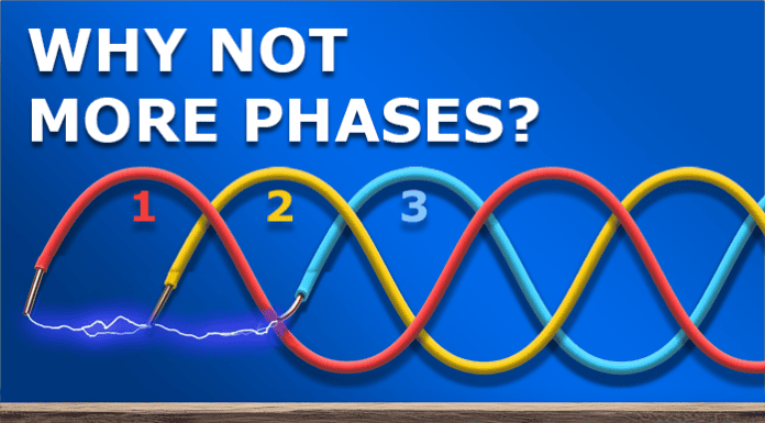
A generator just converts mechanical energy into electrical energy. Typically, they will produce 3 phase AC electricity. Meaning it outputs three separate sine waves, which all occur at slightly different times on 3 different wires.
Inside a basic generator, we find the main housing or stator and then in the centre is a magnet, which is attached to the rotor shaft. We then place three separate coils of wire within the stator.
The rotor shaft attaches to basically anything that rotates. When the shaft rotates, the magnet will rotate and this causes the magnetic field to also rotate. This magnetic field will pass through each of the coils at a different time.

If I rotate this magnet past this coil of wire, we can see it produces a sine wave. The magnetic field interacts with the electrons in the wire and forces them to move. Imagine the north pole is pushing them away and the south pole is pulling them back. The electrons are alternating their direction forward and backwards.
To prove this, we can use LED’s. Because, led’s only allow current to flow in one direction. So, by connecting two led’s in opposite directions, we can tell which direction current is flowing. At normal speed it’s a little hard to see, but in slow motion, we can clearly see only one LED illuminates at a time so the current is definitely flowing forwards and backwards in the sine wave.
The magnet in our generator rotates and pushes the electrons forwards, then pulls them backwards. This will create a single phase, alternating current with a sine wave which repeats every time the magnet makes a full rotation past the coil.
The outlets in our homes provide either 50 or 60 Hertz, meaning the sine wave repeats 50 or 60 times per second. To achieve that, the magnet needs to rotate thousands of times per minute. However, we can reduce the speed by just extending the coil and adding another magnet, because that will reduce the time taken for the north and south pole to rotate past the coil. We can also use gear boxes to increase the rotational speed.

But for now, we will stick to the basic model.
So, we have a single phase generator. The voltage will start at zero, then increase up to the peak positive value and then decrease back to zero. Then on the negative half the value will increase to the peak negative value and again decrease back to zero. This is what the sine wave is representing. Notice, this value changes but the voltage at the outlet is constant, I’ll explain why later in the article.
We can use this to power a load like a lamp, the lamp will increase and decrease in brightness as the current alternates with the sine wave.
As a side note, if you use the slow-motion feature on your smart phone, you can see an incandescent lamp flicker because of the AC current. But It’s too fast for the human eye to see. However, most lights are now LED which are usually constant so you probably won’t see those flicker.

If we look at the output power of this generator, we can see it’s not constant because of the sine wave.
If we add another, separate coil to the stator and position this 120 degrees away, then the coil will experience the change in magnetic field at a different time to the first coil, the voltage generated by the coil will increase and decrease at a different time, so the sine wave will be delayed. This gives us two phases. We can see this will improve the output power, but there’s still a gap.
We can add another separate coil, 120 degrees from the second coil and this will also experience the changing magnetic field at a different time to the other coils, and this gives us 3 phases. We can see this gives us a much more constant output power.
The current is flowing back and forth in each phase, we can prove that with this small 3 phase generator and some LED’s. We arrange the LED’s in pairs of opposite polarities, so that only one will illuminate at any time depending on the direction of current in the wire. We can see they are illuminating, and in slow motion we can clearly see the current is alternating direction.
The coils in the generator are placed 120 degrees apart simply because that gives us even spacing of the sine waves that are produced. We can move the coil to any angle, but the sine wave will also move and we won’t have equal spacing.
You can download my excel sheet and see how the angle changes, as well as the instantaneous phase voltages HERE.
We could add a 4th phase, a 5th phase or 6th phase, but the generator becomes more and more complex and expensive. We also need more cables, more control and protection equipment, complex transmission and distribution infrastructure, more complex transformers and motors etc. It’s then harder to balance the network and it’s very hard to synchronise generators to work together.

So, we instead settled on 3 phase for generators and equipment. Perfect. Oh, but unfortunately each country decided to us a different voltage, frequency and distribution design. Great.
Notice on our generator we have 3 coils but 6 wires. These could all connect to individual loads. But, notice the sine waves change from positive to negative at different times so current flows at different times.
This means we could join the ends of the coils and the ends of the loads together. That allows us to use just 3 wires, which is a lot cheaper. The current will flow back and forth on which ever phase happens to be going that way. We can see on the 3 phase current wave form, at for example 180 degrees, phase A has zero amps flowing. Phase B has positive current and phase C has equal negative current flowing.
This works great for equal 3 phase loads. But with this design we can only connect across two phases, the voltage will be very high. We can’t use this to power our outlets, because it will destroy our appliances.
But, if we reconfigure this into a wye connection. Then we can run a neutral wire from the centre point back to the centre point of the generator. We can also connect this point to ground, meaning this point in the system is zero volts.

If the current is balanced on all phases then no current will flow on the neutral. However, if one phase increases to say 30Amps, then 20Amps will flow on the neutral. The neutral will carry the difference back to the generator or transformer to keep the system balanced.
Because we now have a neutral, we can connect across just one phase and neutral, this gives us single phase. We’re basically just connected across one coil of the generator or transformer. We can do that on each phase.
Or, we can connect to all three phases for larger equipment like motors. This connects us across two coils, but the phases occur at different times, so the voltage isn’t quite double, it’s just the difference between the two sine waves.
We can either connect the three phases in wye or delta configuration. There are different reasons, but basically if the loads were the same resistance or impedance, and the phase to phase voltage was also the same, the current would be larger in a delta configuration, because the loads connect across two phases, whereas the wye connected loads connect to a zero point, so they experience different voltages. The delta can deliver much more power, but it can only power balanced three phase loads. If you need a neutral, we need a wye configuration.

By the way, I have made these cool mugs with the basic 3 phase formulas on, and also my PDF guide, grab yours HERE.
Each power station generates 3 phases, a transformer increases the voltage to hundreds of thousands of volts, this keeps the current and energy loses low over the long transmission distance. When it reaches a city, it enters another transformer which reduces the voltage and distributes this on the sub transmission lines which might feed large industrial or commercial customers, but it otherwise continues to a distribution substation where the voltage is again reduced and distributed along the streets to the properties.
Typically, residential properties are provided single phase connections and commercial properties have three phase connections. Although some parts of the world do provide three phases to homes.
Homes generally need less power, because they have less stuff to power. So, a single phase connection is usually fine. We can also convert single phase into 3 phase using a rotary converter.
If we connect too many appliances to a single phase, we will overload the circuit and trip the breaker. Three phase lets us distribute the power so we can connect more appliances.
A three phase heater will use more energy than a single phase version, but it produces more heat so it does more work. The heat is also consistent unlike the pulsating single phase version.
We could use smaller heaters to get the same heat output with three phases.
We could connect three heaters to the single phase, but they will all pulse at the same time.
The same with electrical motors. Imagine three phase as three people taking turns to rotate the wheel, instead of just one. It’s a smoother rotation and it’s easier to maintain momentum.
The voltage and frequency at the outlets in the properties varies around the world. The multimeter shows a constant voltage value, but the voltage is actually varying significantly, we can see that in the sine wave.
This constant value is the RMS voltage. Which is lower than the peak voltage. We can easily find the peak voltage using this formula.

If we know the peak voltage, then we can easily calculate the instantaneous voltages using this formula.
The sinewave has equal positive and negative values for voltage and current (assuming symmetrical). If we added these all together, we get …zero. So we need a different way to calculate this.
Someone realised that if they connected a DC voltage to a resistor, it produced heat and they could calculate this power. Then they applied an AC voltage and kept increasing the peak voltage until it produced the same amount of heat. The DC voltage was around 70% of the peak AC voltage.
So they did some complex maths, and found if they squared the instantaneous voltages to turn them all positive, added them all and took the mean value, then take the square root of that the value, they got the same AC voltage as the DC voltage. They called this the root mean squared voltage. That is what our multimeter calculates, instead of a constantly changing value.
The local distribution transformer is designed to provide different voltage around the world, depending on the local regulations.
In the UK and Europe, properties are typically provided 230Volt single phase. Or 400Volt three phase, which will also provide 230Volt single phase.
In North America, domestic properties are typically provided 240Volt single phase for large appliances, or they can connect to half of that, to get 120Volt for smaller appliances. The other half will also provide 120Volt, but the sine waves will be 180 degrees out of phase.

Small commercial properties might be provided 208V three phase, which also provides 120Volt single phase.
Larger properties might receive 480Volt three phase, 277Volt single phase. This will power large equipment and then another transformer will reduce this down to 208Volt three phase, 120Volt single phase where needed.
We can also then convert the single phase AC into DC using a rectifier. But that’s a topic for another article.

