

Scroll to the bottom to watch the YouTube tutorial

This industrial site just received a massive penalty charge for something called reactive power. The boss is angry and confused, the electrical engineer tries to explain that his power factor is bad, but the boss is now even more confused. What is the difference and why does it even matter? Let’s find out in this article which is sponsored by Brilliant.
Does power factor apply to DC circuits? NO! The voltage and current are constantly flowing in only one direction, so power factor doesn’t apply. You’ll understand why later in the article. However, it does apply to AC systems that include single phase appliances, but especially three-phase equipment because that usually causes the large penalty charges. A multimeter makes it seem like the voltage and current are constant, but if we use an oscilloscope- we can see that they are not.

It has a sine wave pattern, the voltage and current values are constantly changing, rising and falling with positive and negative values. That’s because the generator is basically rotating a magnetic field, which sweeps past the coils of wire. The coils will experience a changing intensity of the magnetic field. This induces a voltage that basically pushes electrons one way, and then pulls them the other way. This happens 50 or 60 times per second depending on your country’s electrical standard and this creates the 50Hz or 60Hz AC supply. This changing intensity and direction creates a sine wave with positive and negative values. The average of these is zero, so the multimeter just calculates and displays the RMS or Root Mean Squared Values to make it easier to work with. Lets say we measured the RMS voltage and current to a mystery load. If we multiplied these values this gives us something called apparent power, which in this case is 120 volt ampers in DC circuits. This would give us power in watts but not in AC circuits. Instead we measure this in volt amperes. This is how much power is being supplied but it is not how much is actually being used. If we connected an oscilloscope to this mystery load, we can see the voltage and current are not aligned. The current is delayed and lags behind the voltage, which means we have a power factor problem.

We want these to be closer together. Lets assume we measured the delay to be around 1.71 milliseconds and we can easily convert that into degrees. If we take the cosine of this angle, we get a power factor value of 0.8 which is not very good. A perfect power factor would be one, but that’s difficult to achieve, so we often aim for between maybe 0.95 and 0.9. Now if we multiply the RMS voltage and current by the power factor, we get the real power which we measure in Watts. This is the power that’s actually used to do something useful. ideally we would only need to supply this amount of power. This is our target, but we’re supplying more than this because the power factor is bad. What happens if we were to improve the power factor to a perfect one? Well the real power remains almost constant and so does the voltage, which means the current must change. We see the current has reduced which means the apparent power must also reduce by improving the power factor. We can supply less power to achieve the same amount of work, where is this extra power going? We call this reactive power and we can better visualise it with a power triangle. We can draw a horizontal line for the real power, then we can draw another line at an angle to represent the apparent power. The angle between them is that delay we measured on the oscilloscope.
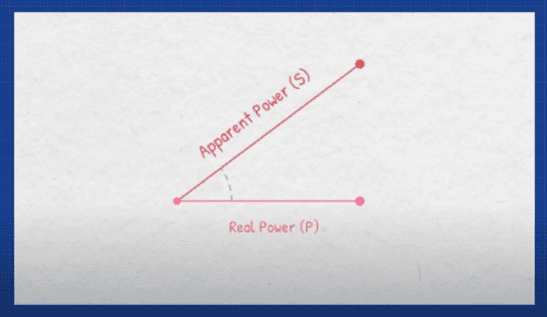
We know we can easily convert the angle into the power factor value, but we can also take inverse cosine of that value, to find the angle. We can also just divide the real power by the apparent power to find this value. From that, you can see that the power factor is just a ratio. So it has no units, now the difference between these two points is called the reactive power- measured in volt amp reactive. I’ll explain what it does in just a moment. By drawing these lines, we form a power triangle, if we have plotted this correctly, then we could just measure this value.

Otherwise, we can calculate it using this formula. Notice that if the power factor value improves, then the angle reduces which brings the apparent power, and the real power values closer together and that causes the reactive power to reduce, and we’ll see how to improve that later in this article. There are various ways to calculate each part of this triangle for real power- we can use these formulas for apparent power. We can use these formulas, and for reactive power we can use these formulas. But where do we find these values? If you are lucky, the electrical panel will have a digital power meter telling you all of these values. Sometimes analog dials are provided and you can read these manually. Ideally, you would have access to a power analyser which provides very accurate and detailed results. Sometimes, the manufacturer will also provide these values in the product data sheet, however you can get these small, cheap and simple versions which just provide the basic values with less accuracy. Or we can use these plug-in versions for portable devices.
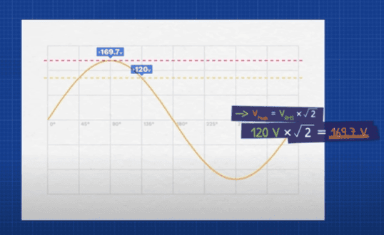
Now the circuit will contain components which can be either resistive, inductive or capacitive. Resistive loads such as incandescent light bulbs convert energy into heat, and light inductive loads such as electric motors store and release energy in their magnetic field. Capacitive loads such as capacitors store and release energy in their electric field, these all affect the circuit differently. Lets understand how and why. Lets say we measure the RMS voltage, this is approximately 70.7% of the peak of the S wave, so to find the peak we use this formula. Then we can use this formula to calculate the instantaneous voltage.
At any point in the cycle of the sine wave, we can see there are positive and negative values. If we took a purely resistive load, we can easily find the RMS current and from that we can calculate the peak current. From that we can calculate the instantaneous current, at any point we again see positive and negative values because current is flowing forwards and backwards. It alternates direction. The voltage and current are in phase with each other, meaning they peak at the same time. This is a perfect power factor. If we multiply the instantaneous voltage and current values, we find the instantaneous power. Notice the power is always positive, even when the voltage and current are negative. We can think of these positive regions as energy leaving the circuit. It’s doing useful work like producing light and heat, the energy only flows one way and that’s out of the circuit. We call this power- real power. In this case all the current flowing through the wire is being used to do useful work which is what we want. However, if we connected a purely inductive load, the voltage and current are no longer in phase, they are shifted by 9 degrees. The current lags behind the voltage, now the instantaneous power has positive and negative values. The inductor will build a magnetic filed around itself, which stores energy. So, during the positive segments, energy is flowing to the inductor to build magnetic field. And then in the negative segment, the field collapses and almost all of that energy is returned back to the circuit. No energy is used, but current flows. The changing applied voltage pushes current in the circuit, creating a changing magnetic field in the wire. But in the coil, that changing magnetic field is going to affect the neighbouring sections of the coil. We know that a changing magnetic field will induce a voltage in a coil, so this magnetic field will also induce a voltage that is going to push back against the applied voltage, that will limit how rapidly the current can increase or decrease which causes the delay in current. But if we connect a purely capacitive load, the opposite happens and the current leads the voltage. We again have the positive and negative segments of power, because the capacitor is storing and releasing energy in its electric field. The current flows to build up the electric field, so the current reaches its peak before the voltage. In both cases we have current flowing through the wire just to just to store and release energy, but its not doing any useful work, its just moving power back and forth. We call this power reactive power. In a normal circuit we usually have some amount of resistance, inductance, and capacitance so the power factor isn’t so extreme.

Typically we have a lagging power factor because of the large inductive loads, but we can correct this by adding some capacitance to the circuit, the reactive power then moves between the inductor and capacitor instead of through the wire. Lets calculate the reactive power, power parent and current for an electrical motor and also how to improve it. By the way you can download my excel sheet with all the calculations and worked examples on HERE,

We also have these very handy mugs with all the formulas on. Check them out HERE.
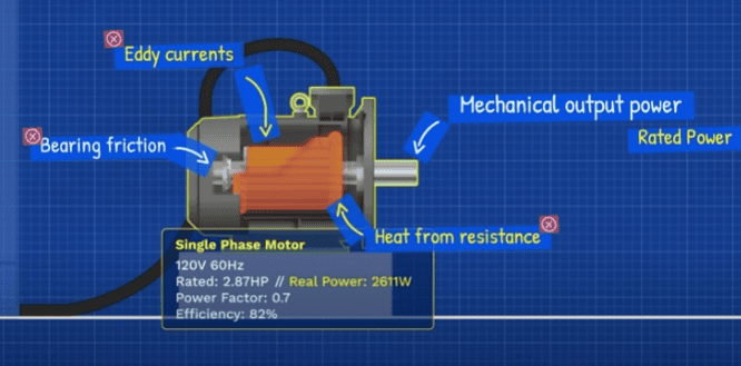
Lets say we have a 120 volt 60 Hz single phase motor rated 2.87 horsepower with a lagging power factor of 0.7 and an efficiency of 82%. We first convert that into Watts, then divide that by the efficiency that is our real power, the rated power is the output from the shaft, but it doesn’t include the energy lost as heat from the resistance, the coil, the friction of the bearings, the heat from the Eddie currents etc.
This is all energy leaving the circuit which we have now accounted for, so we draw a line horizontally to represent that we take the inverse cosine of the power factor value to find the angle, then we calculate the apparent power by dividing the real power by the power factor, that’s the total power that must be provided. To achieve this real power, we know that this line is our reactive power and we can easily calculate that value. Also since we know the real power voltage and power factor, we can arrange this formula to find the current. Now lets see what happens if we increase the power factor to 0.95, well the real power remains the same, the angle has reduced to almost 18 degrees.
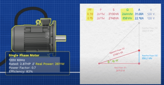
The apparent power also reduces, and that means our reactive power has also reduced. You can see the improvement in the power triangle, this also means the current has reduced significantly. To achieve that, we connect a capacitor in parallel with the motor, the capacitor needs to provide the difference between the two reactive powers. We just calculated the reactive power will oscillate back and forth between the magnetic field of the motor, and the electric field of the capacitor, but what size capacitor do we need? Well this formula calculates that. We know the reactive power, we know the voltage and the frequency, so we can easily calculate the capacitor size. You probably wont find a capacitor rated at that exact size, but we can just test the nearest standard size available, just convert that to farads, drop in your values into this formula, and find the reactive power it can supply. Then subtract from the motors initial reactive power, to find the remaining value. Now that we know the real power and the reactive power, we can find the apparent power. Then we can easily find the power factor which is pretty close to our target, so we can use this capacitor.

The power source will then only need to supply the real power, and the small remaining amount of reactive power. So if that’s just one small motor, imagine what happens inside a large industrial site- with a lot of much larger equipment. You might have noticed that equipment, like generators and transformers are rated in apparent power. So if a large consumer has a bad power factor, then they will take up all the spare capacity of the network with their reactive power, which doesn’t do anything useful. No one else can then be connected to the network, unless an entire new network is installed, or much larger equipment is installed. Both options are very expensive. As reactive power increases, so does the current in the wire, meaning the transmission losses will also be much higher. This all results in the equipment needing to be replaced more frequently. These costs are passed on to the consumers, so the power company will usually issue penalty charges to large consumers to encourage them to install power factor correction. These usually don’t apply to residential customers, as their usage is so small in comparison. it can be difficult to understand and electrical engineering topics, and math behind them. But our sponsor Brilliant is where you learn, by doing. There’s so many new courses but I really enjoyed the new vector’s course, the graphics and interactions just made it so easy to visualise each step, and there was extra help if needed. Brilliant has thousands of interactive lessons in math, data analysis, programming and AI. All the skills you need to become a brilliant engineer. They even have an app, on the-go learning making it easier to build your critical thinking skills through problem solving, not memorizing. Each lesson is filled with hands on problem solving that lets you play with concepts. I think you will enjoy this too. So you can try everything Brilliant has to offer for free for 30 days. Just visit Brilliant.org/TheEngineeringMindset.
")


")


")
