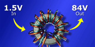
Learn the basics of transformers and how they work in this article.
Scroll to the bottom to watch the YouTube tutorial.
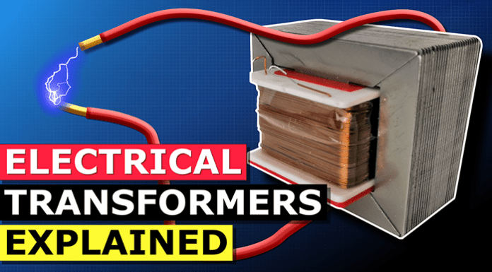
This is a transformer. We find them everywhere, they are essential to our modern life style. They provide the connection between our homes and the electrical power stations. I’m going to show you how they work, why they make this noise, and how to calculate them in this article.
What is a transformer?

Transformers look something like this. We will find them illustrated with symbols like these in electrical drawings. Transformers are simply a device used to transfer electrical energy. It can change the voltage and current in the process, which is very useful. However, they only work with alternating current, they do not work with direct current.
Most appliances are rated in Watts or Kilowatts but transformers are rated with the units VA for volt amps or even kilovolt-amps, we will learn why later on in the article.
We can find small transformers used on door bells or laptop chargers, we have larger versions to supply our homes and businesses and we also find enormous ones which supply entire regions of towns and even cities.
So, where have you seen transformers used, let me know in the comments section down below.
There are lots of different ways to construct a transformer. I have some small common examples here. But, they are essentially just the same thing. They have two separated coils of wire wrapped around an iron core. The generator or supply is connected to one coil, known as the the primary side and then the load, which is the thing we need to provide power to, is connected to the other coil, and this is known as the secondary side.
If I take this one apart, we can see there are simply two separate coils of wire and lots of sheets of iron. That’s it. The transformer is just transforming power between the coils.
Electricity is dangerous so do not try this at home unless you are qualified and competent.
Ok, so. If we use something called a step up transformer, then we can increase the voltage on the output. If we use a step down transformer, then we can decrease the voltage on the output. But, why would we want that? Well, the power station might be producing 12,000 volts. But, your home needs between 120 to 240 volts. The power station is probably a long distance away, so there’s going to be a lot of resistance in the cables resulting in a huge loss of energy on the way.
So, instead, we use a step up transformer to increase the voltage to around maybe 400,000 volts. Then as we reach the town, we use a step down transformer to reduce this back to around 11,000 volts for local distribution, and then reduce it again down to around 240 volts for our homes.
By increasing the voltage through a transformer, we reduce the current. Energy loss in a cable depends on the electrical current and the resistance of the cable.
If this cable has for example 5 ohms of resistance and we try to send 10kW through it at 240 Volts, we would lose about 87% because the current is high but voltage is low, so the losses are huge. But, if we send it at 400,000 volts, we lose a tiny fraction of 1% because the current is low. So we can transmit power further and more efficiently at high voltages.
As a side note, the reason homes in north America can have either 120 or 240v is because they use a 3 wire system, where an additional wire is connected to the centre of the secondary coil. Therefore we can use just half the coil to get 120 volts, or the full coil to get 240 volts. However, most of the world uses around 230 volts, and for this they use just a 2 wire system which is a much simpler design and allows more power to the outlets. And this is useful for example to quickly boil water in a kettle.
By the way I’ve covered residential electrical systems previously in great detail, check it out HERE.
How it works
When we pass an electrical current through a wire, it generates a magnetic field around the wire. If we reverse the direction of current, the magnetic field also reverses. We can see that by placing some compasses around the wire.
When we connect an AC generator to a closed loop of wire, the magnetic field inside the generator is going to basically push and pull the electrons in the wire so they constantly alternate direction between moving forwards and backwards. So, the magnetic field is therefore constantly reversing. The voltage is going to vary between it’s maximum and minimum values because of this. That’s why we see a sine wave pattern if we connect an oscilloscope to a power outlet. This pattern repeats 50 or 60 times per second depending on whether it’s a 50 or 60 hz supply. The AC frequency in north America is 60 hertz, but most of the world it’s 50 hertz. With a transformer, the frequency we put in, is the frequency we get out. We can just increase or decrease the voltage, not the frequency.
When we wrap the wire into a coil, this magnetic field becomes even stronger. The wire has to be insulated with an enamel coating to ensure the current flows along the entire length, otherwise it will just take the shortest route and it will not work.
If we place a second coil of wire in close proximity to the first coil, then the magnetic field will induce a voltage into this second coil because this magnetic field is going to push and pull the electrons in the second coil, forcing them to move. This is therefore a transformer.
The same thing happens if we move a magnet past a coil of wire. The magnet will induce a voltage into the coil.
The key component here is that the magnetic field is constantly changing polarity as well as intensity. This disturbs the free electrons and causes them to move. We call this electro motive force.
However, this only works with alternating current. It will not work if we connect a direct current supply to the transformer. The flow of electrons will still create a magnetic field around the primary coil, but this will be constant and a fixed polarity and intensity. So, it will not disturb the electrons in the secondary side.
The only time it will create an electro motive force using direct current, is briefly when the switch is opened and closed, because this energises and de-energises the magnetic field of the coil, so it is therefore changing. Or, alternatively we could change the voltage, because that will also increase and decrease the magnetic field of the coil.
Notice that when I pass a DC current through this transformer, we get a very brief voltage spike as the magnetic field increases, and also as it decreases. But, if I use an AC supply, we get a constant output voltage because the magnetic field is constantly changing. That’s why we use alternating current.
Now we can just use two separate coils of wire as a transformer, it will work, but not very well. The problem is that we are wasting a lot of the magnetic field, because it’s not in range of the secondary coil. So, we place a ferromagnetic iron core between the coils. This concentrates the magnetic field and guides it to the secondary coil, so that the transformer is more efficient.
However, this is not a perfect solution. It will result in eddy currents flowing around the core which heat up the transformer and therefore wastes energy. To reduce this, the core is made of lots of thin laminated sheets, which restrict the eddy currents movement and reduces their effects. Although we do still lose some of the magnetic field due to leakage flux, and we also get some losses due to the disturbances caused at the joints. We also lose energy in the wire and coils, because they will always have some resistance and this generates heat. So, in a transformer we have copper loss as well as iron loss.
The alternating current causes the sheets to expand and contract tiny, tiny amounts, which causes vibrations between the sheets and that is why we get this humming sound.
A step up transformer works simply by having more turns of wire on the secondary side. This increases the voltage but it decreases the current. A step down transformer works by having less turns of wire on the secondary side. This reduces the voltage but increases the current. Now this isn’t a magical device that produces more energy than it receives.
For example, a step down transformer might receive 240 volts and outputs 120 volts, we see the voltage halves but the current doubles. If we multiply the voltage and current, we see the same value on each side. This is the volt-amp value which is power, or apparent power, and that has to remain the same, so if the voltage changes, then the current has to change in proportion to maintain the power.
Why do transformer use the units of KVA instead of Kilowatts?
The transformer is just transferring power between coils, so we use the volt amp units. The kilowatts depend on what you connect to the transformer. The manufacturer doesn’t know what you will connect to the transformer so they state the total rated apparent power in volt-amps. And that’s because in AC circuits, the load depends on the true power in kilowatts multiplied by the power factor, which is basically efficiency and this varies depending in the device.
Some energy is consumed but it produces no work, it is just wasted as heat, and we call this reactive power, with the units V.A.R. Power factor is just the ratio of true power and apparent power. (PF=KW/KVA)
If you think of a glass of beer. The liquid beer is the useful stuff, this is your true power in kilowatts. But, there is always some foam, which is useless, we don’t want that. This is the reactive power or volt-amp reactive. You pay for the total volume of the glass, regardless of how much foam and beer is inside, this is your apparent power, in volt amps. If you have a good bartender, you get a little foam and lots of beer for your money. If you have a bad bartender, then you are going to get lots of foam and not much beer for your money.
The transformer manufacturer is basically saying the transformer can handle a glass this big, but it’s up to you how much beer and foam you put into that. The less foam you try to pass through, the more beer you can get out. So, the more efficient the device you connect, the more things you can power.
Transformers are also often used in rectifier circuits to convert alternating current into direct current. The transformer reduces the voltage and then some diodes convert this into a rough direct current, a capacitor then smooths it out into a nice clean power supply. You can learn how that works in detail in out previous article HERE.
Basic Transformer calculations
Lets run some basic calculations for transformers, assuming it is perfect with no losses.
If we had a transformer with 1,000 turns on the primary and 100 on the secondary, and we supplied it with 120 volts, what voltage would we see on the secondary? We can use this formula to find that out, and we see the answer is 12Volts so this is a step down transformer.
What if we only knew the output voltage and the amount of turns. Well, we could find the input voltage using this formula; and we input the values to get the answer.
If we wanted to find the number of turns on the secondary side and we knew the voltages and primary turns, then we could use this formula to get our answer.
If we wanted to find the number of turns on the primary ide, we could use this formula and that will give us the answer.
If we had a current of 1.2 amps on the secondary, then we find the primary current using this formula and we see the answer is 0.12 amps
We could also find the answer if we knew the secondary current and both voltages, using this formula
If we knew the current on the primary side and the voltages of the primary and secondary, we could find the secondary current using this formula or we could also find the answer using this formula.
We then check that the power is the same on both sides of the transformer by multiplying the voltage and current.
Lets now consider some step up transformer examples
If we had 100 turns on the primary and 200 on the secondary and we supplied it with 120 volts, what voltage would we see on the secondary? We can use this formula to find that, so we see the answer is 240V, this is therefore a step up transformer.
What if we only knew the output voltage and the amount of turns. Well, we could find the input voltage with this formula.
If we wanted to find the number of turns on the secondary side and we knew the voltage and primary turns, then we could use this formula.
If we wanted to find the number of turns on the primary, we could use this formula.
If we had a current of 1 amps on the secondary, then we find the primary current using this formula and we see the answer is 2 amps.
We could also find the answer if we knew the secondary current and both voltages, using this formula.
If we knew the current on the primary side and the voltage of the primary and secondary, we could find the secondary current using this formula or we could also find the answer using this if we knew the number of turns.
We check that the power is the same on both sides of the transformer by multiplying the voltage and current.

