

Centrifugal pump basics. In this tutorial we’re going to be looking at the centrifugal type pump. The centrifugal pump is the most common type of pump used in industry, and it’s used in pretty much every commercial and industrial buildings as well as houses, apartment blocks even ships and some aircraft will have some form of centrifugal pump installed.
Scroll to the bottom to watch the YouTube tutorial on Centrifugal Pumps
Larger sites, especially commercial and industrial buildings, will likely have multiple sets of pumps. This is to serve the different systems they have within the building. Typically used for heating and cooling systems, or anything where water needs to be pushed around some pipework throughout the building or a manufacturing process.
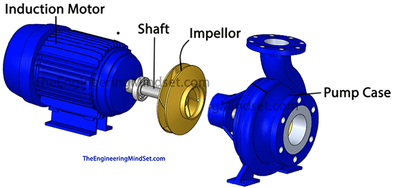
In a typical setup, an induction motor is mounted at the back. The shaft is then run between the rotor of the motor, over into the pump, and the impeller is then mounted to the shaft and would sit inside the pump casing.
The induction motor rotates the shaft, which, in turn, rotates the impellor.
Changing the speed of the motor will change the speed of the impellers rotation. In this method you can then change the water flow rate of the system.
The impeller sits inside the pump casing, where it’s completely sealed in, you won’t be able to look inside it or any of its components.
The centrifugal pump has two ports, an inlet, and also an outlet. The inlet is always through the centre, usually on a horizontal axis, as is refereed to as the suction line. Whereas the exit is on the vertical axis and this is known as the discharge line.
The impeller should always be submerged in water, otherwise it will not be able to draw sufficient flow and operate correctly. Insufficient flow can cause cavitation, where the water inside actually starts to boil due to the low pressure, this can cause severe damage to the pumps impellers.
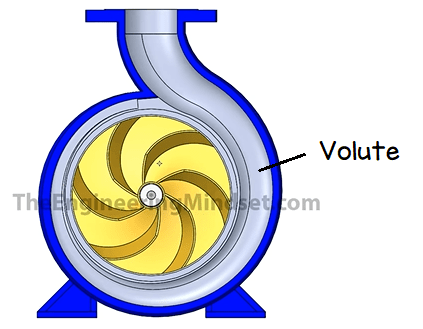
The pump casing has a volute running around it’s circumference. The volute has an increasing diameter all the way from the start, where it’s smallest, around to the discharge where it’s at it’s largest diameter. This change in diameter allows more water to flow which means an increase in the mass flow rate as the water accumulates.
The water starts by entering into the pump through the inlet port. As the water enters into the impeller, it’s rotating force pushes the water outwards into the volute. The volutes increasing diameter directs the flow of water to the outlet.
The impeller has a number of curved vanes which run from the centre all the way out to the outer edge. This type of impeller is known as the backwards curve type impeller, which is the most common and most efficient design for moving water.
It’s important to remember that these veins do not push the water out like a paddle, the water actually flows in between these and the veins help provide a guiding force.
When the impeller begins to spin, it creates a low pressure suction at the inlets.
This low pressure suction pulls the fluid into the center of the impellor.
We know that when you spin something, it always tries to move away from the centre, away over to the outer edge. Imagine spinning a ball attached to some string. The ball moves outward and is held by the string, if the string snapped then the ball would fly off into the distance.
Centrifugal forces

Looking at how the forces involved to move the water. We have the rotational force of the impeller. As rotating objects try to move away from the centre of rotation, we have an outward force. The water particles will have inertia from the rotating force. When we combine the outward force with the inertia we get a resultant force at an angle. This gives us our spiral trajectory path which the water will take.
As the water collects in the volute, it slows down and this converts its kinetic energy into static pressure. The water continues to flow in behind this and this is what pushes the water, allowing it to maintain pressure, as well as it’s flow rate. This allows water to be pushed through pipes all the way around the building. That is why they are used throughout buildings and systems all around the world.
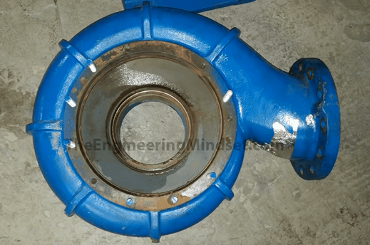
Above you can see an example of the volute casing. The water flows in through the central hole away from the camera (a plate is missing from the image, the hole is smaller), and then hits the impeller and is spun off into the volute and out the top of the casing, which is the flanged plate on the right.

Above you can see an example of a real pump impeller. The water flows inside the central hole and into the rotating impeller vanes.
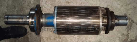
Above is a pump shaft with the induction motor rotor on the right side and the seal on the left end.
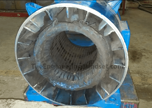
Above you can see an example of the inside of an induction motor. The rotor of the motor will sit inside here with the pump seal sitting outside, towards the camera.
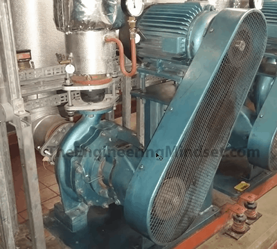
The pumps might not be coupled directly to the motor, sometimes they’re belt drive like the example above. This is less energy efficient because the belts will slip and we have frictional losses. If you can, use direct drive, they’re much more efficient and also far less maintenance involved.


")
")
 Pressure Enthalpy Chart")


")

")


")
Thank you for explaining all the different components of a centrifugal pump, like the induction motor, shaft, and impellor. That’s so cool how it uses centrifugal motion to pump the water in a circular way. My cousin works in a facility that requires centrifugal pumps, so it’s nice to understand how they work!
thank you to explain all this secret information of the pumps , shaft etc, assist me about more information, i am student at west gate training center in Zimbabwe
Great Resource, appreciate all the effort and time building this website!
Centrifugal pumps can provide the most cost-effective solution. Attributes include high efficiency, low power consumption, low noise level & easy maintenance.
[…] Electric Motor-Driven Centrifugal Water Pump. Image by TheEngineeringMindset.com […]
Well understood.