

Sponsored by Fluke.
How RCDs and GFCIs prevent electric shock. Many people think a standard circuit breaker (MCB) protects them, but it only protects wiring. In this article we explain RCD / GFCI protection, how they work, and when they fail.
Scroll to the bottom to watch the YouTube tutorial.
This device can detect an electric shock and cut the power fast enough to save your life. But, it doesn’t always work. So we tested the reaction speed, then ripped one apart to see what’s inside and learn how it works but we also learn when it will not work.

But this one, a standard circuit breaker, won’t save you at all. It was never designed to.
A standard breaker trips for only 2 reasons. First: a short circuit. That’s when a live and neutral wire touch directly, there’s almost no resistance so hundreds or even thousands of amps flow instantly. And the breaker trips immediately.
The second reason: overload. That’s when too many loads are connected, causing the current to slowly increase past its rated value, which causes it to trip. Otherwise the cables will overheat and start a fire.
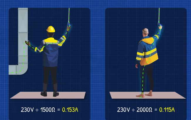
Both of these are only designed to protect the wiring, not the people. The problem is, your body has a high resistance. So if you touch a live wire, the current flowing through you will be too small to trip most standard breakers. But, it will still be more than enough to stop your heart. So the breaker remains on and the shock continues. However, there is one situation where it can save you. That’s if the live wire touches a properly grounded metal enclosure. That creates a short circuit, so the large current trips the breaker. But, if the enclosure isn’t properly grounded, the breaker won’t trip, and the enclosure is energised, so if you touch it, current can flow through you.
So how do we actually protect people from an electric shock?
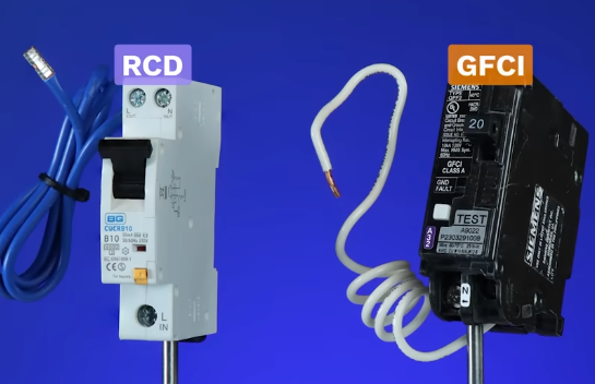
We use these devices called RCDs, or GFCIs in North America. Different names, but they all use the same working principle. They continuously monitor the current flowing into and out of the circuit. Under normal conditions, those two currents are identical.
Subtract one from the other, and you get zero. But during a fault, that balance is broken. Some current leaves the circuit where it shouldn’t, often through a damaged cable or a human body. That imbalance is called residual current, which is why in the UK these devices are known as Residual Current Devices.

But, Because this fault current usually flows to ground, these devices are called ground fault circuit interrupters in North America. Other parts of the world simply call them differential circuit interrupters.
These devices come in many shapes and sizes, depending on manufacturer and also how they are used. An RCCB only protects against ground faults, nothing else. Because of that, it’s often used to protect multiple circuits at once.
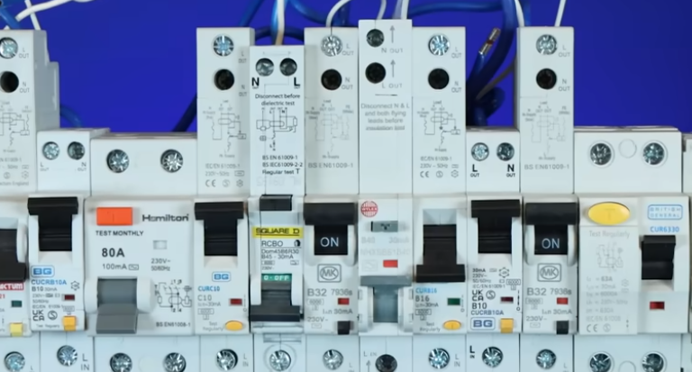
Each individual circuit still has its own breaker for overloads and short circuits, but the RCCB monitors them all for current imbalance. Protecting the entire home from one device. The downside is if it trips, it cuts power to all the circuits it protects.
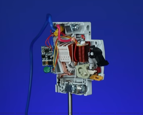
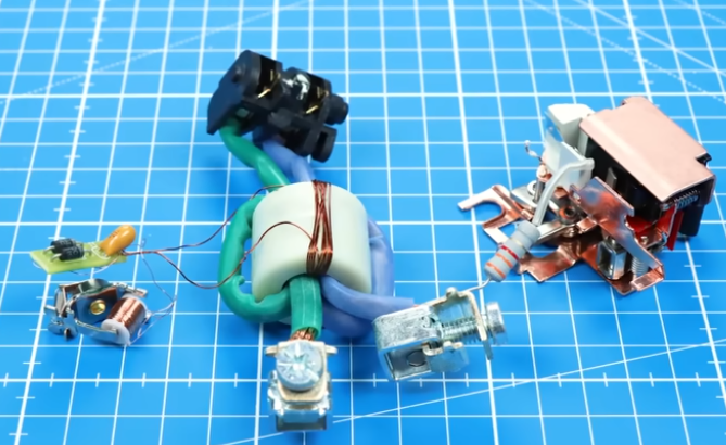
These devices are surprisingly simple. They’re mostly electromechanical, just a toroidal transformer, a solenoid, a basic circuit board, a resistor and a mechanical latch. They trip at relatively large fault currents, so they don’t need complex electronics.
Newer installations often use RCBOs instead. These combine ground fault, overload, and short-circuit protection into a single device,
so each circuit is protected independently.
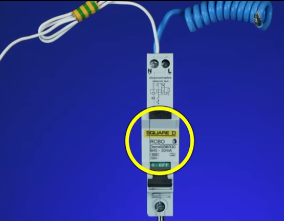
They are thinner than RCCB’s because they use electronics to amplify and filter the fault signal, which allows for a much smaller toroid.
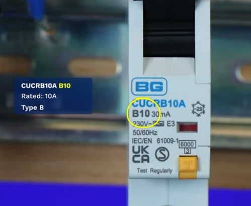
This number gives us the over current rating, and the letter defines how it trips under overloads and short circuit conditions only, not earth faults.
In the US, a GFCI breaker is typically used. This only protects that specific circuit, not the entire home. Alternatively, a GFCI outlet is used, with a standard breaker.
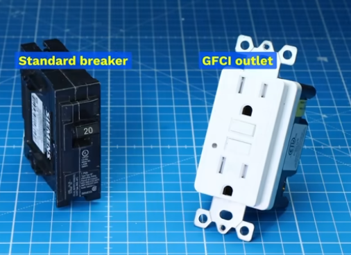
This will protect everything downstream of it in that branch, but nothing upstream of it. We have a dedicated article explaining exactly how that works if you’re interested.
These devices need much more complex circuitry because they must trip faster and at much lower fault currents.
That requires additional filtering to prevent false trips.
Let’s understand how they work.
In a normal circuit, current flows from the source to the load and then back to the source. Our homes use AC, or alternating current so the current constantly changes between flowing forwards and backwards. But, for simplicity lets use DC, direct current, which is only one direction. The important thing is, the current flows to the load and then back, so the current is the same in both wires.
But, during a shock, some of the current flows through the person and then through the ground to get back to the source. It doe not return via the neutral wire. So at that moment, the currents in the wires are not equal. So, there must be a fault.
But, how do we detect that and cut the power? Whenever current flows through a wire, it creates a magnetic field around it.
The larger the current, the stronger the magnetic field. If the current changes direction, the magnetic field also changes direction. We can see that by placing some compasses around a wire.
If we coil the wire, the magnetic field from each loop will add together, forming a larger stronger magnetic field. Alternatively, we can place it around a ferrite core and this magnetic field will swirl around the core. We call this magnetic flux and it can be used to induce a voltage into another conductor
For example, If we connected another coil around this core, that magnetic flux would pass through the coil. When a constant magnetic field passes through a coil, nothing happens. But when the magnetic field changes, a voltage will be induced in the coil, this induced voltage will create a current.
See, when the current is constant, nothing happens. But when the current increases (or decreases) the magnetic flux will also increase (or decrease), and this second coil generates an induced voltage and current. Essentially, this coil can sense, or detect a change in current. – Hence the name sense coil.
The problem is, our homes use AC, so the voltage and current are constantly changing. That means the sense coil is always detecting a changing current. And the RCD needs to account for that.
Remember, current is flowing in opposite directions in the wires, and the direction of the magnetic field depends on the direction of current. So if we also wrap the neutral wire around the core, its magnetic flux will cancel out the live wires magnetic flux. So the sense coil will stop detecting the constantly changing AC currents.
This completes the first stage/section/part of a RCD. With balanced AC, the live and neutral wire currents cancel each other’s magnetic flux, and the sense coil doesn’t detect anything. Even when more loads are connected, the current will be equal so it won’t detect any changes.
But, when a shock occurs. Some of the current leaves the circuit, so the current won’t be equal. The live wire will have more current, so the magnetic field and magnetic flux will be stronger through the core.
This will cause the sense coil to generate a small induced voltage.
To make this small voltage usable, we see a lot of turns on the sense coil which will increase the voltage and sensitivity. This version has 1 primary and 10 secondary turns. For simplicity, let’s keep 1 primary and 10 secondary turns and use direct current.
So, when a shock occurs, the imbalance will generate an induced voltage in the sense coil and will push a current to… another coil which has a substantial number of turns. This is the second and final stage/section/part of an RCD
Remember, when current flows through a coil it creates a magnetic field. Well we can use that to move a piston. This is called a solenoid.
So we can use that to activate a mechanical latch, opening the circuit and cutting the power.
It happens so fast that you might miss it if you blink it.
This is basically how an RCD works but it doesn’t end here. It can get more complex and more interesting (to avoid say better)
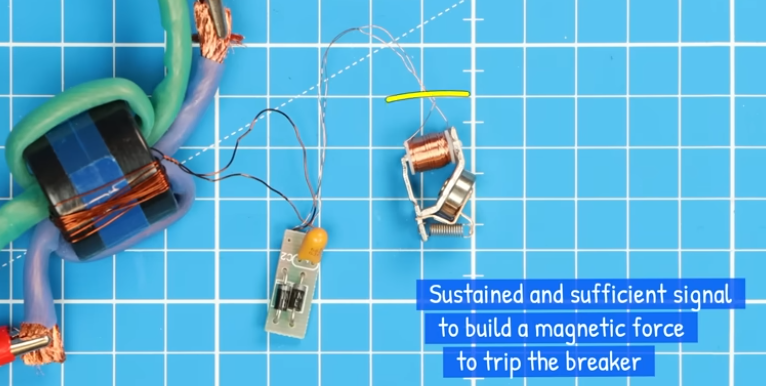
In some RCD circuit boards diodes are used to clamp and limit the sense coils voltage, while capacitors shape the time response, filtering out brief or small signals but allowing sustained and sufficient ones. Helping to drive enough current through the solenoid to build the magnetic force needed to trip the breaker.
Other versions use a small magnet to hold a spring loaded lever in position,
when the coil is energised, the magnetic field generated releases the lever and the spring forces it down,
This will hit another lever which activates the mechanism.
So when a person is shocked, the current imbalance through the toroid causes an induced voltage and current in the sense coil, which is sent to a solenoid to open the circuit and save the person.
The electronic versions still use a toroid to detect the fault signal, but an electronic circuit will basically filter this, then rectify it, and use it to charge a capacitor.
If the voltage reaches the trip threshold, a comparator outputs a signal which then triggers an SCR, and that energises the solenoid and trips the breaker, cutting the power.
This all happens almost instantly. The RCD then remains off until the fault is cleared and someone manually resets the mechanism.
So we know how they will protect us, but when will they fail?
Well an RCD doesn’t prevent a shock. It just limits the duration of the shock, the longer current flows through you the more dangerous it becomes.
But, if the fault occurs before the RCD, it will not trip. Also, if you touch the live and neutral at the same time, the RCD will not trip. Because the current is the same in both wires.
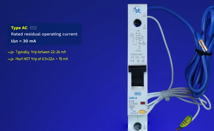
It will only trip if enough current leaks through you to ground. But, right here it states it is rated to trip at 30 milliamps imbalance,
it will trip slightly below this, but it is not allowed to trip below 15mA,
We will test it in just a moment.
However, larger currents are more dangerous so it must trip faster if that occurs.
But, we can get 100 and 300mA versions, these are only designed to prevent fires, not people. However, many older installations use Type AC RCDs, marked with this symbol.
These were designed to work with sinusoidal AC currents, like incandescent lamps. But modern electronics like LED lights, laptop chargers and USB chargers all distort the current wave form.
Additionally, faulty devices like EV chargers can leak DC into the neutral. The problem is, DC current creates a constant magnetic field, and this will be applied to the RCD’s core.
The core can only handle so much magnetism, so this steady DC can push it toward saturation. If an earth fault then occurs, the current imbalance tries to create a magnetic field, but the core is already overloaded, so it can only produce a small amount.
This weak signal can be insufficient to operate the trip mechanism, so the RCD won’t trip. If you test the energised RCD, and it doesn’t trip, that could be why. That’s why type A rcd’s are now used. This symbol shows they work with AC and pulsed DC.
Then there’s type F, designed for variable frequency equipment as well as AC and pulsed DC.
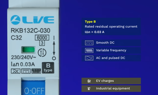
Finally there’s type B which offers the highest protection, covering smooth DC, variable frequency, pulsed DC and AC. Essential for EV charges and industrial equipment.
So the right type must be used. If you want to be protected. But, how do we know these devices actually work?
Notice the device has a T button, for testing. It must be energised to work. But when pressed, it should trip the device.
It basically just sends current from the live, through a large resistor straight to the neutral, creating an imbalance to trip the device.
But to really test it, we need a multifunction installation tester, luckily our sponsor fluke kindly sent us one.
It can check everything from voltage, continuity, insulation resistance, loop and line impedance, earth resistance, phase rotation, surge protection and voltage drop.
But we want the RCD test.
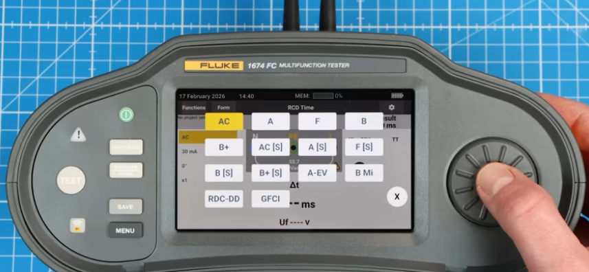
The breaker we’re testing is a Type A, so we will select that from the options. It is rated for 30mA so we select that for our test current.
We can choose the phase angle, 0 or 180 degrees, but for now I will use 0 degrees. Then we select the multiplier factor, I will first use 1x, meaning it will inject 1 times 30mA RMS fault current.
There is also an info button which tells us how to connect the device. So when safe and ready, we start the test, the breaker trips, and we see the time taken.
In the UK it must trip in under 300 milliseconds, which is 15 cycles, we are definitely below that so this is fine, and It shows a pass on screen also.
If we change the phase angle to 180 degrees, this test can give a different result. This alters where in the waveform the fault begins which affects how quickly magnetic flux builds in the core, which changes the trip time.
Next we select the 5x multiplier, which injects a 150mA fault current, that will trip the breaker and we see the time is much faster, that’s because the danger has increased.
But, If we change to the 0.5x multiplier, it will inject 15mA, but when we run the test, the breaker doesn’t trip. The test stops at 310ms as it exceeded the time limit, the device is not allowed to trip at or below 15ma so this is a pass.
To find the minimum trip current, we need to use the rcd ramp function. Ensure the device type is correct, the rated current is set and select a phase angle. Then run the test and we see it tripped at 21ma imbalance and it took 31.1miliseconds to achieve that.
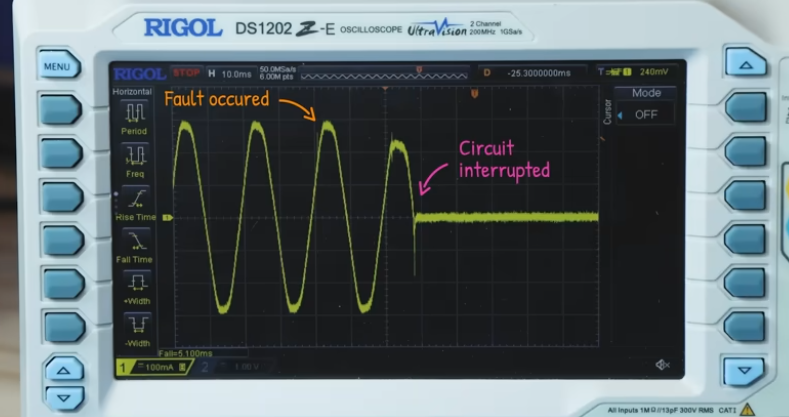
That is all within limits so this is a pass. We can also see this with an oscilloscope. I’ll clamp the live wire, which feeds an incandescent lamp. That gives us this nice current sine wave.
Now, I’ve already setup my trigger settings, so when I press single capture button, then press the rcd test button, we can capture the trip on the oscilloscope. We can see a disturbance in the wave form, from where the fault occurred and we can see where the circuit was interrupted.
There’s also a spike on the final peak, which is likely where the mechanical latch started to open. If I use the cursor feature, placing the A line on this start point, then move the B line to the end point, we can see the trip time listed here. Which is very close to what we saw on the fluke device.
Now these results will be different each time, depending on where the fault started in the cycle which occurs when you press the button.
But anyway, that is how this device works to save your life, and if you’re interested in the fluke device, check them out HERE.


")


")

")


 protects them, but it only protects wiring. In this video we explain RCD / GFCI protection, how they work, and when they fail.)