

How Multi Ejectors work in CO2 transcritical refrigeration systems. In this article we’re going to be discussing the multi ejector as well as its application and working principle for transcritical CO2 refrigeration systems. We’ll cover the basics of RAC systems in configurations of Booster system, Parallel compressor and parallel compressor with integrated Multi Ejector.
Scroll to the bottom to watch the video tutorial – includes full animations!
🏆 Learn more about the Danfoss Multi Ejector SolutionTM at: http://bit.ly/Multi-Ejectors
When paired with the technology in the Danfoss Multi Ejector SolutionTM, CO2 enables refrigeration systems to outperform traditional HFC systems in terms of energy efficiency in all climate zones, while reducing the impact on our environment—it’s the ultimate win-win.
Now, even the hottest regions like the Middle East, Southern and Latin America, Australia, and Asia can enjoy all the benefits that CO2 has to offer. Find out more about what has Danfoss saying, “We Love CO2” at ➡️ http://bit.ly/Multi-Ejectors
In a previous article, link here, we discussed how traditional HFC refrigerants are starting to be phased out through new laws and regulations because of their damaging effects on the atmosphere and environment. This means alternative refrigerants are being used and there’s a growing trend to use CO2 as a refrigerant, which is referred to as R744.
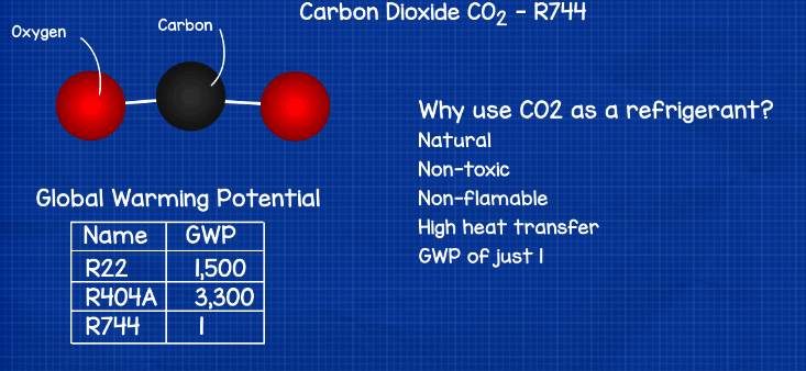
R744 is popular because it is a natural, non-toxic and non-flammable refrigerant with high heat transfer and a Global Warming Potential of just 1. It’s growing in popularity especially within supermarket or food retail refrigeration systems with many R404A and R22 systems being replaced with R744 (CO2).
Traditionally R744 has been used mainly in the cooler climates especially in northern Europe, and that’s because in the cooler climates it operates very efficiently whereas in the warmer parts of the world where the ambient temperatures are at or over 27°C (81°F) we find that historically R404A is more efficient than R744.
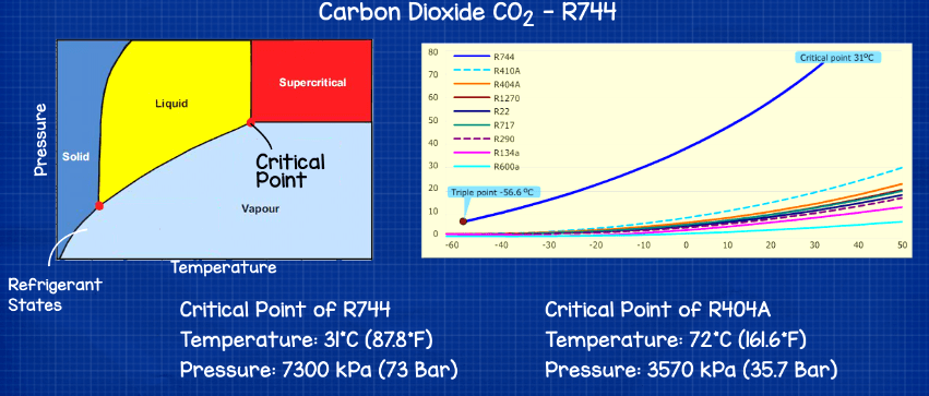
The reason it has mostly been used in northern Europe is because the critical point of R744 is very low at just 31°C (87.8°F) and 73bar (7300 kPa) where as R404a has a critical point at 72°C (161.6°F) and 35.7 bar (3570 kPa). Therefore, when the ambient temperature is near or above this low critical point, the refrigerant is unable to undergo a phase change and condense into a liquid within the condenser. The cooling capacity of the evaporator is reduced, in a standard transcritical system, and higher pressures at the gas cooler are needed to increase the cooling capacity. However, Danfoss has found a solution to the problem and launched the multi ejector to allow CO2 transcritical systems to operate efficiently even in the harshest conditions.
Let’s have a look at some simple systems to see where the multi ejector is located and how it works. We’ll consider the system operating in transcritical mode with an ambient temperature of ~33°C (91.4°F).
Booster Refrigeration System
A typical simplified 1st generation CO2 Booster System would have a design much like a standard refrigeration system with the compressors compressing the refrigerant and sending this to the condenser or gas cooler to reject the unwanted heat.
By the way in CO2 systems you’ll often hear the condenser referred to as a gas cooler, that’s because, as I mentioned earlier, when the ambient conditions are above the critical point, the refrigerant can’t condense into a liquid so the refrigerant is in a gas form and the condenser only cools this gas down, therefore we call it a gas cooler instead of a condenser.
The refrigerant then passes through a high-pressure control valve which is controlling the pressure of the refrigerant within the gas cooler. It then flows into the receiver which separates the refrigerant depending on whether it is in a gas or liquid state.
The refrigerant which is in a gas phase will flow through a bypass line and valve into the suction line of the compressor where it will repeat the cycle.
The refrigerant which is in a liquid state at the receiver will flow down and take one of two routes, depending on the system design. In this example the refrigeration system is supplying both refrigerators and freezers so we have two different pressure lines.
The first line is the medium temperature line which supplies the refrigerators. The refrigerant flows through an expansion valve and into the evaporator to provide cooling by removing the unwanted heat, it then takes this unwanted heat and makes its way to the compressors.
By the way if you want to learn how expansion valves or evaporators work, we’ve covered these in great detail previously, link here.
The second line feeds the freezers and is therefore a low temperature/pressure line. Again this flows through an expansion valve and evaporator but this time it enters an additional compressor to bring the pressure up a bit, it will then re-join the other refrigerant and flow to the main compressor to repeat the system.
In this design we have 100% of the refrigerant flow rate coming out of the gas cooler and into the receiver, around 45% will be in a gas state and flow through the bypass whereas the remaining 55% will flow to the evaporators. The main compressor therefor has to work hard trying to compress 100% of the refrigerant through the system.
Parallel Compressor Refrigeration System
The second generation CO2 system added a parallel compressor which took the gas state refrigerant from the receiver and compressed this separately. In this design, around 45% of the refrigerant will enter the parallel compressor while only 55% enters the main compressor. This made the system more efficient because the gas state refrigerant coming from the receiver is at a higher pressure compared to that coming from the evaporators so less work is needed to bring this back to high pressure for the gas cooler. The main compressor now only has to do work on the remaining 55% of refrigerant so it too has a reduced work load.
Multi Ejector SolutionTM
The third generation design and the most energy efficient CO2 system design to date uses the multi ejector with an AK-PC 782A pack controller. In this design we run a line from the suction line of the main compressor and feed this into the multi ejector. We also take the high-pressure line from the gas cooler and feed this in too.
These too different pressure refrigerants are going to be mixed together and feed into the receiver. In this design the multi ejector will lift around 40% of the refrigerant from the suction line of the main compressor and mix this with the flow from the gas cooler. 60% of this mix will flow to the evaporators and 80% is going to flow to the parallel compressor. Therefor only 20% is compressed by the main compressor which has to work the hardest and the remaining 80% goes through the parallel compressor.
How does the Multi Ejector work
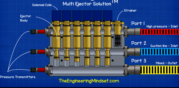
If we look at the multi ejector you see we have 3 ports on the side, the top port is the high pressure inlet from the gas cooler, the middle inlet port is the lower pressure intake from the suction line of the main compressor. The bottom port is the outlet where the mixed refrigerant will leave the multi ejector and head to the receiver.
On the other side we have 3 pressure transmitters which are being monitored by the controller.
On the top we have a strainer which all the refrigerant from the gas cooler will enter through to protect the system.
We then have 4-6 ejectors to control the flow of refrigerant through the multi ejector, these are controlled by solenoid coils on the top which are connected to the controller.
If we look inside the unit we see the main body of the ejectors. The two streams of inlet refrigerants enter the multi ejector and are held in the headers. The controller will signal one or more solenoid valve to open depending on the capacity required.
As the solenoid is energised it lifts the respective valve needle to allow the high-pressure refrigerant to start to flow into the ejector.
It enters through the top which is known as the nozzle. The refrigerant then passes through a small contraction in the cross-sectional area known as the throat, this causes the refrigerant to expand. During the expansion the potential energy of the high-pressure refrigerant is converted to high speed kinetic energy.
By the time the refrigerant reaches the exit of the nozzle it’s at a very high velocity. As you might know from fluid dynamics, when velocity increases the pressure decreases. This reduction in pressure causes a suction as the refrigerant passes across the opening for the 2nd inlet, this suction causes the check valve to open and then pulls the gas state refrigerant in from the suction line of the main compressor.
These two refrigerants will then mix together in the mixing chamber or mixing unit.
The mixed refrigerants will then enter the diffuser which is a conical shape. This expansion in cross sectional area slows the refrigerant down and so the velocity or kinetic energy is converted to potential energy or pressure. This medium pressure refrigerant then flows to the receiver.
Each ejector within the unit is rated for a different capacity so the controller will vary how many and which ejectors are being utilised to provide the optimal performance.


")

")


")
[…] previously covered other types of cooling systems for commercial buildings, supermarket co2 systems, chillers and chilled water schematics. Do check those out if you haven’t […]