Scroll to the bottom to watch the YouTube tutorial.

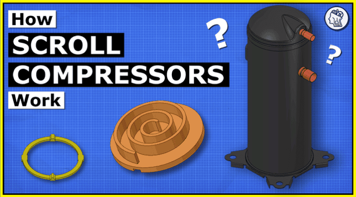
Scroll compressors look something like this. They come in many shapes and sizes depending on their capacity and also the technology used inside. They convert electrical energy into mechanical energy.
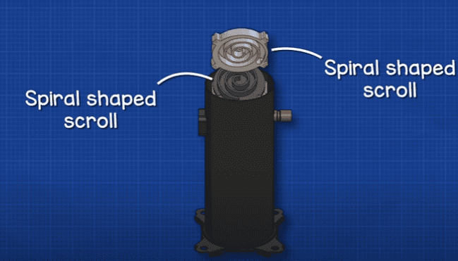
We call them scroll compressors because inside we find two metal spiral shaped scrolls which causes the compression.
We can find them used in equipment like air compressors, but we will be focusing on the refrigeration versions for this video. We commonly find them used in air conditioning systems, heat pumps, rooftop units, CRAC units, walk in coolers, and we also find them grouped together for larger commercial cooling applications.
Compressors are the heart of the refrigeration system, pushing the refrigerant between all the components. The refrigerant is a special fluid which can easily change between a liquid and gas.
The compressor pushes this around the entire refrigeration system, through the condenser, expansion valve and evaporator and then back to the compressor.
Compressors simply trap a quantity of refrigerant and then compact this into a smaller volume to increase the pressure. The molecules are tightly packed together so they collide more, the pressure and temperature increases.
We send this high temperature, high pressure (superheated vapour) refrigerant outside to the condenser, which is a simple heat exchanger. The hot refrigerant flows through the tube while cooler ambient air is blown over the outside of this tube. The refrigerant is a much higher temperature so the heat flows from the refrigerant, through the tube wall and into the air.
The removal of heat causes the refrigerant to condense into a liquid. It leaves the condenser as a high pressure, medium temperature, liquid and flows to the expansion valve. These are either mechanical or electronic design. You can watch our detailed videos on how they work.

But they basically use a sensor to monitor the superheat at the exit of the evaporator. Then open and close the valve in small amounts to control how much refrigerant can flow through the evaporator, which controls the superheat value.
Superheat basically means the refrigerant has been boiled to a point where it is completely gas, no liquid can exist at that point.
The nozzle of the expansion valve holds back the liquid refrigerant, as it passes through it will expand into the empty.
Just like a spray bottle, we force liquid through a nozzle which vaporises it, and it expands into a liquid vapour mixture.
With more space, we have a drop in pressure, the molecules can move around more so the temperature drops.
This then flows into the evaporator which is another heat exchanger inside the property.
The refrigerant again flows through the tube, with the air of the room flowing over the tube,
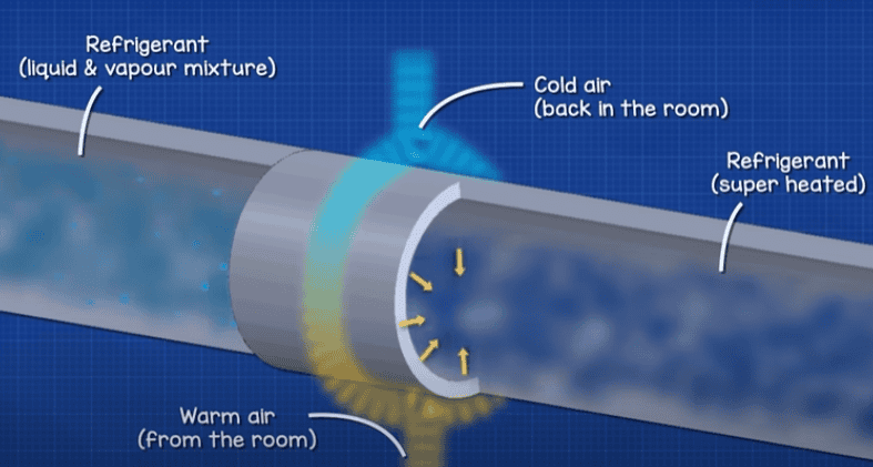
But this time the thermal energy of the air is going to flow through the tube wall and into the low pressure refrigerant.
The low pressure allows the refrigerant to boil very easily.
Just like this vessel filled with low pressure refrigerant. My hand has enough thermal energy to cause it to boil.
The heat of the room is enough to boil the refrigerant, because it has a very low boiling point.
The refrigerant turns into a gas and carries the unwanted heat of the room away.
It exits as a low pressure, low temperature slightly superheated vapour. The refrigerant is then sucked into the compressor.
When we look at the compressor we have the main protective shell, we also find the low-pressure suction inlet and the high-pressure discharge outlet. There is also an electrical connection for the power supply and controls.
This is hermetically sealed, meaning all the components are sealed inside, so we can’t access them but dirt also can’t enter and the refrigerant can’t escape .
When we remove the shell, we see there is a mechanical section and an electrical section.
At the bottom we usually find some type of support with a bearing built into this. The shaft will sit within this bearing and rises up through the compressor. Connected to the shaft is the rotor.
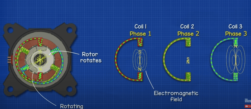
Surrounding the rotor is the motor stator. There is a small gap between the stator and rotor. The stator remains stationary but the rotor rotates. The stator has a number of coils of wire, these are energised and create an electromagnetic field. The magnetic field interacts with the rotor, causing it to rotate. The rotor is attached to the shaft, so this also rotates.
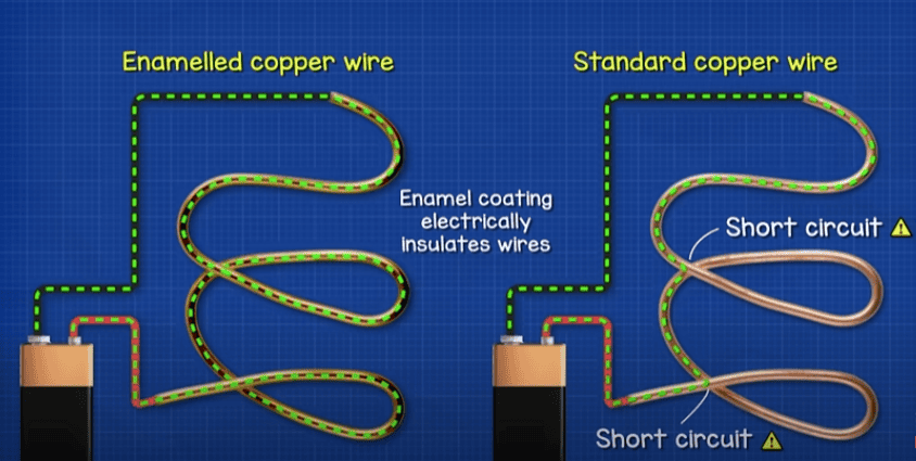
Attached to the coils is a temperature sensor, typically this is a PTC type sensor. As the coil temperature increases, the PTC resistance increases. At a certain temperature the sensor will cut the power to protect the motor. Otherwise the heat of the coil will melt the enamel insulation causing a short circuit and the stator would burn out.
Coming back to the shaft. We can notice the top of the shaft is offset from the centre. The scroll will attach to this. But because the scroll is offset, we have an imbalance on the shaft, so we find some counterweights attached at the top and bottom of the rotor to correct this.
At the top of the shaft we find the compressor housing. We usually find a bearing within this to support the shaft during rotation.
The housing has some grooves cut into it. Another component, called the Oldham ring, has some ridges which will sit within these grooves, allowing it to slide back and forth. The orbiting scroll also has some grooves cut into it, these will interlock with the ridges on top of the Oldham ring, allowing the scroll to slide back and forth perpendicular to the housing and Oldham ring.
The offset of the shaft, combined with the restrictions of the oldham ring, allows the scroll to orbit without rotating on its axis.
The orbiting scroll will sit within a fixed scroll. This is connected to the shell and also the housing, so it is locked into position. When the shaft rotates, the orbiting scroll will now move within the fixed scroll. This causes compression, we will see how that works in just a moment.
The compressed refrigerant is then ejected from the centre. We typically then find a non-return valve here, this design is a simple disc valve that is pushed open to vent the refrigerant, and it drops down when the compressor turns off to stop backflow. We might also find reed valves used, these are basically thin sheets which bend to open and vent the refrigerant but will also drop down when the compressor turns off. Above this we usually find a heat shield. The refrigerant leaving the compression chamber is high temperature, so this helps prevent heat transfer back into the compression chamber.
Notice there is a void between the heat shield and the shell, this stores some refrigerant. The refrigerant will exit the compression chamber in pulses and so this storage chamber removes these pulses allowing a constant stream to exit the compressor.
Some compressors will have a check valve at the compressor outlet instead of the compression chamber. But It works in a similar way.
We might also find some sort of pressure relief valve built into the housing. if the discharge temperature exceeds the design limit, it will discharge the hot refrigerant gas down into the casing, the motor winding temperature sensor will detect this rapid increase in temperature and cut power to the motor.
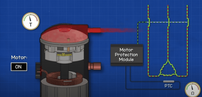
In the bottom of the housing we find a reservoir of oil and residual liquid refrigerant. Some compressors will have a sight glass where you can inspect the oil level. Inside the shaft there is a small channel with various exits points and an opening at the lower section. As the shaft rotates, oil is sucked into this opening and the centrifugal force causes it to rise up the channel. It will exit at various points to lubricate the bearings and surfaces.
The refrigerant is sucked into the shell from the evaporator. It will typically hit some sort of shield plate because the refrigerant will be a mixture of liquid and gas. The liquid will then drop down to the reservoir while the gas can continue to flow.
The refrigerant will then flow inside the casing, through and around the motor. It seems strange, but remember the motor is sealed within the shell. A standard electrical motor uses a fan to blow ambient air over its casing and remove the unwanted heat from the stator. Electrical motors produce a lot of heat which needs to be removed or it will destroy the motor.
So, we use the refrigerant to collect and remove the heat. The refrigerant will then flow upwards and into an opening on the side of the fixed scroll.
As the scroll orbits, the walls will separate and a gap opens to allow some refrigerant inside. The scrolls then continue to orbit and the gap closes, a pocket of refrigerant is now trapped inside. The walls will continue to orbit and this forces the refrigerant to move deeper into the compression chamber towards the centre, gradually the volume decreases which increases the pressure.
Eventually the refrigerant will reach the centre where it has reached maximum compression, the scrolls then separate at the very centre allowing the refrigerant to escape, the scroll continues to orbit and the central gap closes which forces any remaining refrigerant to exit and it then collects in the dome at the top.
During compression, several pockets of refrigerant will be compressed simultaneously. Which gives a continuous output.
Scroll compressors can handle small amounts of liquid. It will pass through without damaging the scroll plates.
The refrigerant exits the compression chamber as a high pressure, high temperature superheated vapour and flows to the condenser. A crankcase heater is sometimes fitted, this keeps the shell warm in cold climates to prevent the refrigerant condensing inside, prevents backflow and also stops the lubricating oil from diluting.
Traditionally scroll compressors would just be turned on and off to control the cooling capacity. The system is either completely on or completely off, no in-between.
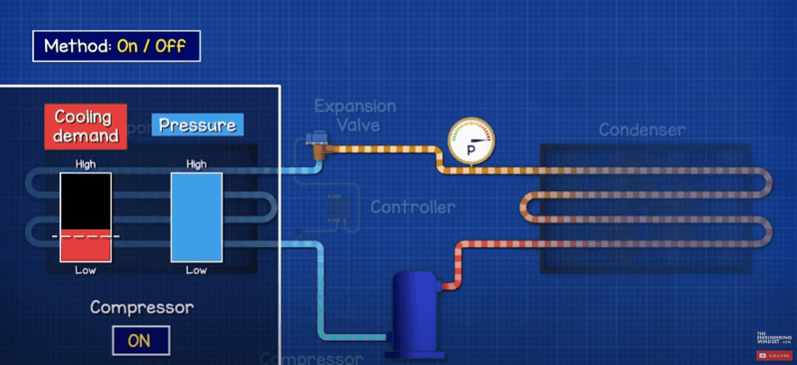
On larger systems with a group of compressors, they would simply be turned on or off at different stages to try and meet the cooling demand. This gives some modulation of capacity but it isn’t perfect.
Turning the system on and off causes pressure surges, bad thermal control and also causes electrical surges.
The electrical motor has a fixed speed so the only way to modulate the cooling capacity was to turn it on and off.
The diameter of the scroll, the height of the scroll wall and the motors rotational speed controls the capacity. These were all fixed properties of the design.
One method developed, known as a hot gas bypass, which uses a solenoid valve to recirculate some hot refrigerant back into the evaporator, . This creates a false cooling load on the system. It’s very inefficient but it keeps the compressor running.
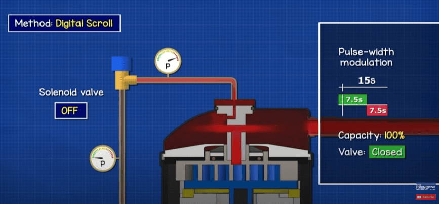
Another common design is the digital compressor. A solenoid valve recirculates refrigerant back into the suction. The fixed scroll can move up and down. The pressure within the dome holds it down. But a solenoid can open to release this pressure back into the suction line. The scrolls disengage a tiny amount, so no refrigerant is compressed in this time but the motor keeps running, the valve then closes, pressure forces the scroll down and compression continues. We control this in 15 second intervals so If you need 50% capacity, then the scroll will engage for 7.5 seconds and disengage for 7.5 seconds.
Newer designs use a variable frequency drive to control the speed of the motor, so that the volume of refrigerant flowing around the system changes to match the current cooling demand. This uses an electronic expansion valve to achieve precise control. Giving us great energy efficiency and also optimal thermal control.

