

Learn how vacuum pumps work, the main parts and why we use them. This article details the basic working principle of single stage and two stage vacuum pumps for HVAC engineers. For more articles on HVAC engineering CLICK HERE.
Scroll to the bottom to watch the YouTube tutorial.
What Are Vacuum Pumps?
Vacuum pumps are used extensively by air conditioning and refrigeration engineers to remove air or non-condensables such as water from the system. We need to remove these from the system because they cause the refrigeration system to operate inefficiently and can also corrode the internal parts.
This procedure is carried out before a new system is charged or when an existing system has undergone some repairs where the refrigerant has already been recovered. In either case there’s a chance air and moisture have contaminated the system.
Where Are They Connected?
On a typical air conditioning system you’ll see these vacuum pumps connected via a manifold across the high and low pressure side of the system. A better way to do this is to remove the manifold and connect the vacuum pump to the suction line with a pressure gauge connected to the liquid line as that’s the furthest point in the system so you get a true reading.
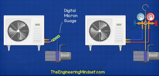
We’ve teamed up with our friend Bryan over at HVAC school for this article. His YouTube video runs you through how to actually connect a vacuum pump to a real world system as well as give you lots of great technical tips to build your knowledge and skills. To watch his YouTube video out CLICK HERE.
The Main Parts Of A Vacuum Pump
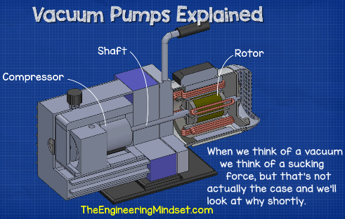
If we take a standard vacuum pump that looks something like below.
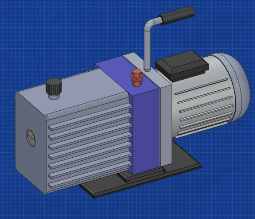
We have the electrical motor on the back, the compressor at the front, a handle on top and a support base on the bottom. We then have an inlet which connects to the system to remove the air from the system and we also have the exhaust to disperse this to atmosphere. On the front of the compressor section we will find an oil level sight glass so we can tell how much oil is in the chamber as well as it’s condition.
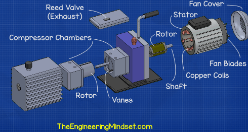
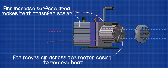
As we take the unit apart, we can see we have a fan and protective casing mounted at the back of the motor. Inside the motor we have the stator with coils. Concentric to this; we have the rotor and the shaft which drives the compressor. At the front we have the compression chamber. This is a two stage compressor version which allows us to pull a deeper vacuum so we therefore have two compression chambers. Inside the chambers are the compressor rotors and the vanes which moves the air out of the system. On top of the compression chamber is a reed valve which vents the exhaust. When we remove the fans protective case, we see the fan is connected to the shaft which runs through the pump. The fan is used to cool down the electrical motor and will blow ambient air over the casing to dissipate this. The fins on the casing increase the surface area of the casing which allows more unwanted heat to be removed.
Inside The Motor
Inside the motor we have the stator which is wound with copper coils. When an electrical current flows through the copper coils it generates a magnetic field. The rotor is affected by this magnetic field and this forces it to rotate. The rotor is connected to the shaft and the shaft runs along the length of the pump from the fan to the compressor. This way; when the rotor rotates so will the compressor and that’s what we use to create the vacuum effect and evacuate the air from a system.
Just to note, when we think of a vacuum; we think of a sucking force but that’s not actually the case. We will detail why further below.
Inside The Compressor
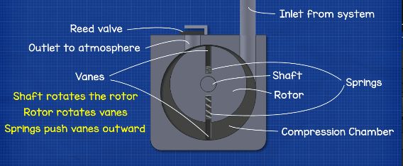
If we look inside the compressor, we can see we have the inlet, which is connected to the system we’re evacuating. We then have the outlet and the reed valve which vents the air and moisture which is extracted.
In the centre we have the compression rotor and the compression chamber. Notice the rotor is eccentrically mounted inside the chamber, meaning it isn’t perfectly central, that’s a key feature which we will see in detail below. The shaft connects to the rotor and will cause it to rotate.
Mounted inside the rotor are two spring loaded vanes. The springs are always trying to push the vanes outwards but they’re held in place by the compression chamber walls. The tips of the vanes are always in contact with the wall and there’s a thin layer of oil which helps form a seal between the two. When the rotor rotates, the springs continue to push the vanes outward so the vanes will follow the contour of the compression chamber.
When the pump starts, the rotor is going to move across the inlet and expose an area inside the compression chamber. This area will be at a lower pressure compared to the pressure inside the system; so the air and moisture inside the refrigeration system is going to rush in to try and fill this empty region.
Why Does It Do This?
Pressure always flows from high to low, so if we connected for example; two balloons of different pressures, the gases will move from the high pressure side into the low pressure side until both are of equal pressure. The low pressure side was a vacuum, but it didn’t suck the gases in, the high pressure side pushed its way in. That’s the vacuum effect. Gases want to equalise and will flow from a high pressure to a low pressure. Gases try to equalise pressure across connected regions.Therefore we use a vacuum pump to create a region of lower pressure so that the unwanted gases
inside a refrigeration system will rush out of the system to try and fill this lower pressure region.
In our scenario, the connection hose and the new low pressure area within the compression chamber become an extension to the refrigeration system so the gases in the system are going to rush to fill this and try and make the pressure between these two equal. However, it’s a trap, because as the rotor continues to rotate the second vane sweeps in and traps that volume of gas in the chamber between the two vanes. The other vane passes across the inlet and creates another lower pressure region so more gases rushes in to fill this void again and again. As the compressor rotates, the volume of the chamber is going to start to decrease, that’s why the rotor is not perfectly centered so we can vary the volume of the trapped gases. This decrease in volume is going to compress the gases into a tighter space, that will increase the pressure and temperature.
It continues to rotate into a smaller volume until the pressure becomes high enough that it forces the reed valve at the exhaust to open and the gases are discharged.
The compressor continues to rotate and as it does so the next batch of gases is pulled into the system and this cycle continues.
Most vacuum pumps will be two stage which means there are two compression chambers linked in series, with the exhaust from the first compressor linking directly into the inlet of the second chamber. This design allows the pump to achieve a deeper vacuum.
Two Stage Design
When we have a single compressor; the outlet is pushing against atmospheric pressure, as detailed above. But with the two stage design, the outlet is pushing against a much lower pressure which is simply the inlet of the second rotating compressor and the low pressure region it creates during that rotation.
As the vacuum pump continues to run, it will eventually pull the gases out of the closed system which will reduce the pressure down below the pressure of the atmosphere that surrounds the outside of the system.
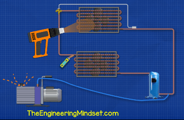
As the pressure reduces, any moisture in the system will become easier to boil and evaporate. We can add a little heat with a heat lamp or heat gun to help it vaporise.


Hi Paul,
Thank you for this excellent webpage showing how a vacuum pump functions. I am super interested in understanding this topic. And when I see the animation of a single stage rolling piston vacuum pump functioning and read the accompanying description, something really puzzles me. Could you possibly tell me,
Why is an exhaust valve required for steady operation of the vacuum pump?
I can understand why an exhaust valve would be required, and need to be closed, if the vacuum pump is slowing down, so that the vacuum attained in the system is retained.
What happens if the exhaust valve is held open during continuous operation of the rolling piston vacuum pump?
I am guessing the vacuum pump would at least be very noisy, with atmospheric air rushing in for each cycle. Would the atmospheric air rushing in disturb the smooth rotation of the rotor? (Thus making operation of the pump less efficient, perhaps?)
Could a single stage vacuum pump be designed and built, with slightly altered positioning (and shape) of the inlet and outlet ports, so that an exhaust check valve was not necessary (closing, opening, closing, opening etc.) during continuous operation? (And maybe a different type of valve could be utilised for the times when the pump slows down – towards a halt.)
Thanks a lot if someone could provide some insight. Thank you for creating the excellent presentation.
Kind regards,
Matthew S.
Hi Paul,
(Maybe this message has already been received. I was not sure the sending occurred.)
Thank you for this excellent webpage showing how a vacuum pump functions. I am super interested in understanding this topic. And when I see the animation of a single stage rolling piston vacuum pump functioning and read the accompanying description, something really puzzles me. Could you possibly tell me,
Why is an exhaust valve required for steady operation of the vacuum pump?
I can understand why an exhaust valve would be required, and need to be closed, if the vacuum pump is slowing down, so that the vacuum attained in the system is retained.
What happens if the exhaust valve is held open during continuous operation of the rolling piston vacuum pump?
I am guessing the vacuum pump would at least be very noisy, with atmospheric air rushing in for each cycle. Would the atmospheric air rushing in disturb the smooth rotation of the rotor? (Thus making operation of the pump less efficient, perhaps?)
Could a single stage vacuum pump be designed and built, with slightly altered positioning (and shape) of the inlet and outlet ports, so that an exhaust check valve was not necessary (closing, opening, closing, opening etc.) during continuous operation? (And maybe a different type of valve could be utilised for the times when the pump slows down – towards a halt.)
Thanks a lot if someone could provide some insight. Thank you for creating the excellent presentation.
Kind regards,
Matthew S.
Hi Paul,
I’m building a vacuum fryer chamber (20liters) using 1/2hp rotary vane pump to remove air while the chamber is cooking at 80-100C. I was thinking of using the same pump for my condenser recirculation water where the hot air/oil mixture vapor will pass through before it exit into an aspirator pump into the water reservoir. Do you any idea or layout how to do it. thanks
[…] the cylinder valve leak test, the water passages are closed by plugging them. You also need a vacuum pump to help you determine if there’s a pressure drop due to cracks. After closing off the water […]
[…] items. In its basic form, the machine consists of a hot sealing bar to seal a package shut and a vacuum mechanism to evacuate air from the […]
[…] Pumps Explained: https://theengineeringmindset.com/vacuum-pumps-explained/How to Use a Vacuum Pump: […]
[…] Quote from the source: … […]
[…] Quote from the source: … […]
[…] used for a variety of purposes such as heating, cooling, and chemical reactions. Understanding the basics of vacuum pump technology is important for anyone looking to use and maintain these powerful […]