

Learn how and where liquid level switches are used within ammonia industrial refrigeration systems. We’ll look at the main parts, the applications as well as the technology inside.
Scroll down to watch the YouTube tutorial
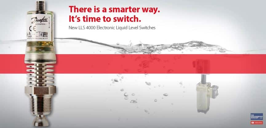
🎁 See the Danfoss LLS 4000 HERE
It’s time to make the switch to electronic liquid level switches. The LLS 4000 liquid level switch from Danfoss makes commissioning and installation much easier, and its SIL2 rating guarantees reliability. Plus, you can commission and monitor the switch using Danfoss’s new smartphone app.
So in our first article on industrial refrigeration we looked at the main system components for single stage, two stage and cascade systems. If you haven’t read that article already you can find it HERE
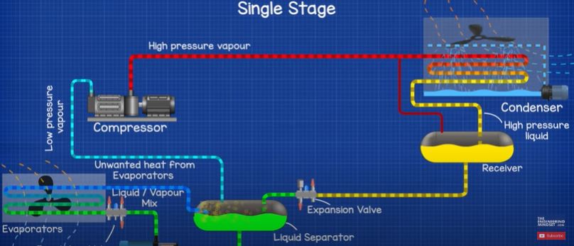
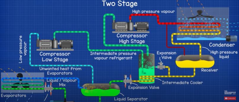

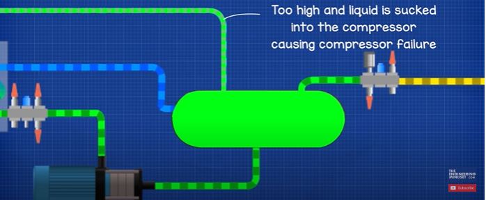
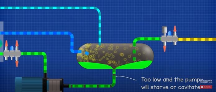
In each of these systems we saw a number of vessels which accumulate and release refrigerant to maintain the stable operation of the system. In these vessels we have a mixture of liquid refrigerant as well as vapour refrigerant. The liquid level rises and falls during the operation of the system and the cooling demand experienced by the system. Now we don’t want the liquid level to get too high or too low in these vessels, we need to maintain the level between our defined upper and lower limits in order for the system to operate smoothly. If we don’t maintain this then we’re going to run into all sorts of problems.
The vessels and pipes are metal so we can’t visually see inside them. We can install sight glasses and liquid level gauges but these will require constant manual readings. We need an accurate and autonomous way to sense if and when the liquid level is at the limits and automatically alarm the engineers to the issue.
So for that we use digital liquid level switches which look something like this.
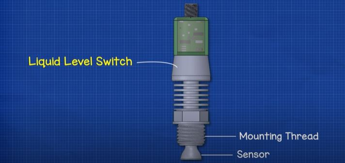
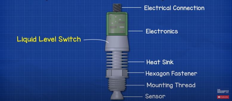
At the end of the unit we have a sensor, we will look at how this part works in detail later in the article, but this part is going to be in contact with the refrigerant. Then we have a thread which will allow us to connect the device into the system and seal it in place. There is a hexagon head just above that which we use to tighten the device into the fitting in our system. Then we have a heat sink, this is just going to dissipate the unwanted heat from the electronics, we want to remove this heat to ensure the electrical components last a long time and don’t overheat, these fins just increase the surface area and allow us to dissipate more heat into the ambient air. Connected to this we have the electronic circuit board which has a protective casing and on the top we have the electrical connection which will power the device as well as allow electronic communication with the system controller.
How and Where Are LLS’s Used?
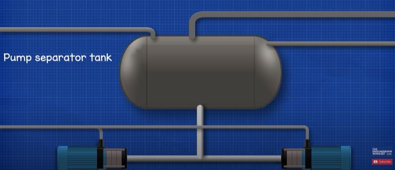
Let’s say for example we have this pump separator vessel in our ammonia refrigeration system. We want to ensure the liquid level of ammonia refrigerant stays between an upper and lower limit.
Mounted to the side of the vessel we have a column; we will probably find some sight glasses built into this and we might even have a liquid level gauge mounted to the column. Both simply allow us to visually inspect the level of liquid refrigerant in the vessel.
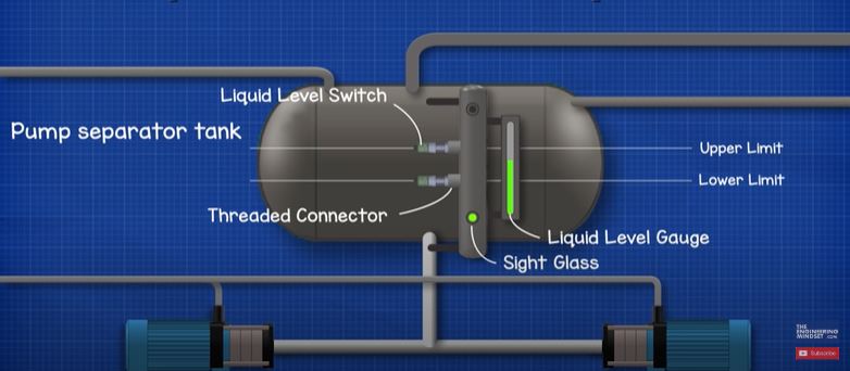
On the column we have two threaded connectors which our liquid level switch will be screwed into. These are positioned between the upper and lower limits for our vessel for the liquid level we want to maintain.
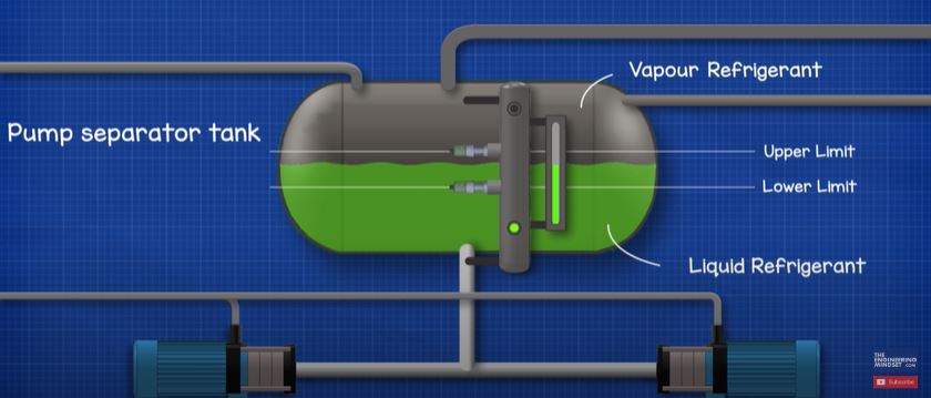
So, as we can see, the bottom level switch is submerged in liquid refrigerant while the top switch is within the vapour refrigerant region. That’s what we want, because it means that the liquid level is within our desired limits so the system is in normal operation.

The device is detecting the difference between liquid and gas so when installing the device, we would need to pay attention to the potential for gas pockets. For example, if we installed the device in a horizontal position then as the liquid level rises and falls any gas pockets will naturally dissipate. But if we installed the device vertically, then there is potential for gas to become trapped within the enclosure. This is going to obviously affect the reading of the sensor and we won’t get accurate results.
We have previously covered purging ammonia refrigeration systems, you can find it HERE
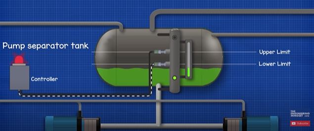
Coming back to the column installation. We could face the problem that the liquid level drops, in this case the liquid level is going to come below our lower limit switch. The sensor will detect that phase change from a liquid to a vapour and will send a warning signal to the system controller.
Additionally, we could face the issue of over fill where the liquid level becomes too high in the vessel. This means the liquid refrigerant will rise above the upper sensor. This sensor will also detect there has been a phase change from vapour to liquid and will again send a warning signal to the system controller.
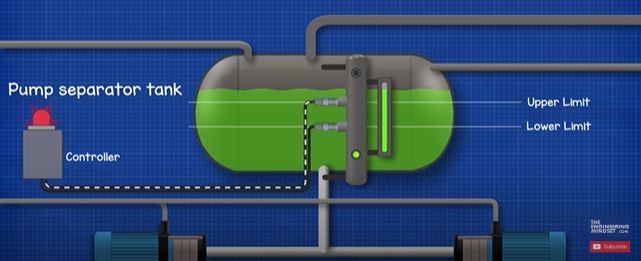
In either case the switch activates an inbuilt relay which is used to sound an alarm and can be connected to the system PLC or programmable logic controller.
How Does The LLS Work?
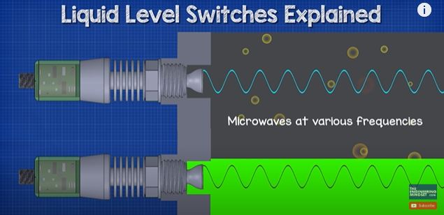
The device uses a technology known as reflectometry which emits a microwave at various frequencies from the sensor and into the fluid, these rebound back to the sensor with a pattern. Each fluid and the different states of the fluid create a different pattern.
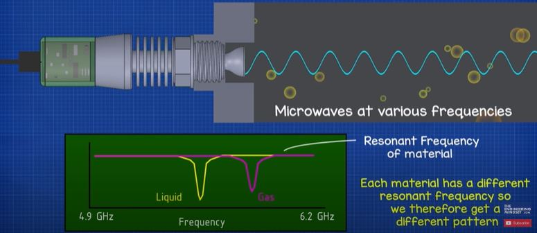
The pattern is the resonance frequency of the fluid and each material has a different resonant frequency so we therefore get a different pattern. Liquid has a much lower frequency compared to air so we have these different plots.

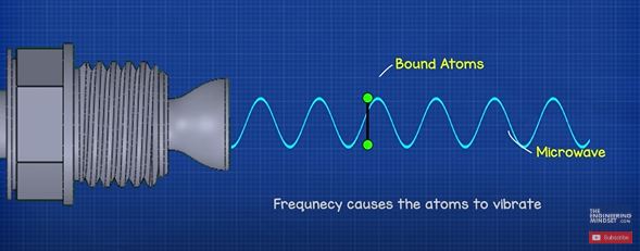
The resonant frequency is the frequency that causes the atoms of the material to vibrate. So, looking at a very simplified example, the sensor emits a microwave at a certain frequency over some atoms which are bound together, this frequency has no effect on the atoms and they do not vibrate. But as we vary the frequency through a spectrum, we will find a frequency that causes the atoms to vibrate, as we continue through the frequency spectrum, the vibration stop. So by measuring these vibrations of atoms across a frequency spectrum we can plot this pattern.
A number of refrigerants are tested and the results recorded by the manufacturer into the device. So once we configure the device and specify which refrigerant our system is using, the device can correlate it’s measurements with the known properties and thus we have our digital liquid level switch that can detect liquid or vapour and relay an alarm if the system goes into fault.


