

Fan Coil Units. In this article, we are going to be looking at FCU’s. FCU stands for fan coil unit but often engineers will just call them a fan coil, to save time. Fan coil units are very common in all types of buildings, from offices, bars, canteens, even some homes and apartments will have a fan coil unit in them. Fan coil units are used to condition the local air to suit the temperature requirements of the immediate space.
Scroll to the bottom to watch the YouTube tutorial on Fan Coil Units
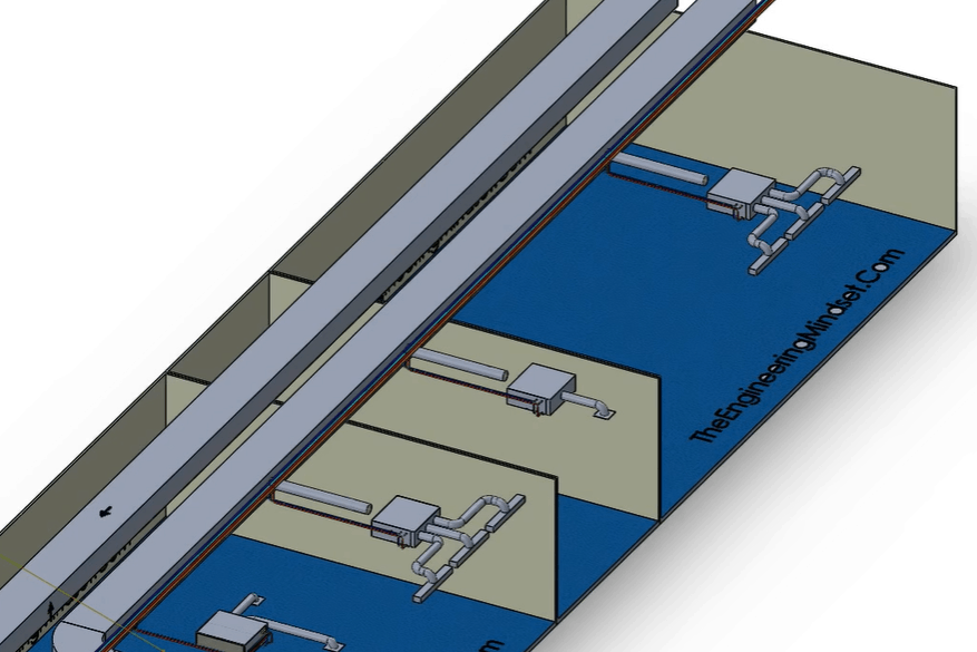
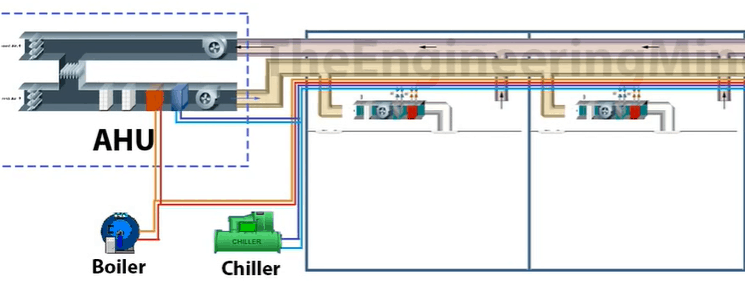
As illustrated in the above image. There are two main ducts (supply and return) which will go around the building to supply the various rooms. Coming off the supply duct is a round duct supplying the fan coil units. The fan coil units are connected to either a heating coil, a cooling coil or both heating and cooling coil. These will condition the air. A motorised fan inside the fan coil will then force the air out into some smaller, localised, ducts to strategically distribute the air within the room.
In this model you can see the main AHU which is supplying fresh air to the building via the main supply duct. These run out all over the building taking the shortest route for efficiency. Branches will come off of this and they will feed fresh air into each room. Each room will need a certain volume of fresh air supply per hour. This fresh air is directed into the back side, the inlet, of the fan coil unit but this branch isn’t usually directly connected to the unit, there is a gap between the two. There is a reason for that, which we’ll look at later.
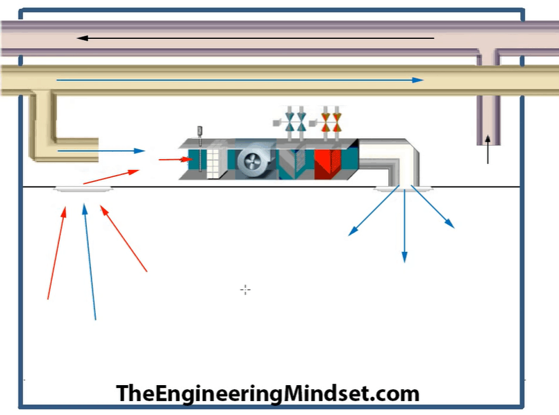
A motorised fan will suck the fresh air into the fan coil unit. The fan will force the air across the heating and/or cooling coils before forcing it our through the localised diffusers.
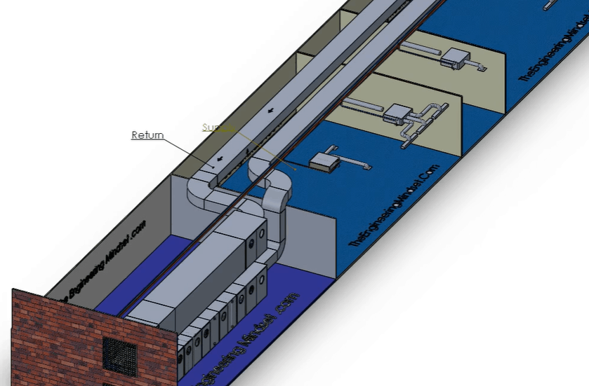
Once the air enters into the room it will provide the heating/cooling to the occupants or equipment inside. It will then take one of two routes. It will either be sucked into the return grille and be sucked back into the AHU via the return duct. Otherwise it will be pulled back into the fan coil unit via a grille in the false ceiling.
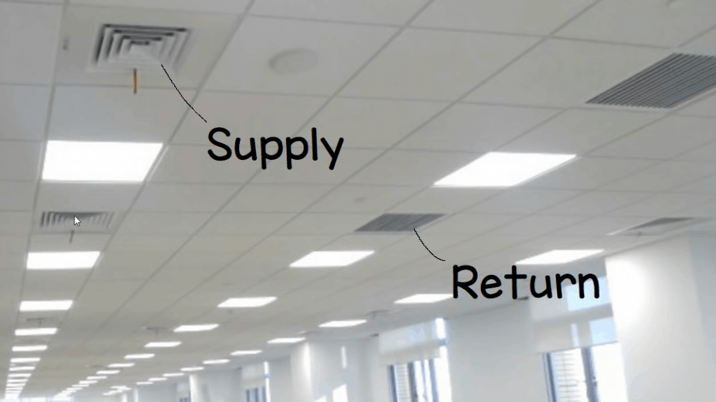
The Fan Coil Unit is located up in the ceiling. I’ve shown an example above of a false ceiling typical of an office. There are two types of vents in the ceiling, the diffusers which distribute the air into the room and the return grille which sucks the air back in.
The air will return via the return duct. It will be pulled into the ceiling void. Some of the freshly treated air can be wasted by being pulled directly back into the void even though it hasn’t been of any use to the room. This can be mitigated with good design. Once in the void the return air will mix with the fresh air and be pulled into the fan coil unit. Otherwise the main return duct will suck this air in and take it back to the AHU.
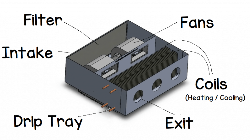
Fan Coil Units are a fairly simple design. You can see where it gets it’s name from because it basically just a fan and a coil heat exchanger.
The air enters via the back through a filter to clean the air from dust etc. The filters can just be pulled off to be cleaned or they can be replaced.
Once that air is pulled through the filters it enters into the fans. Typically a fan coil will have 1-3 fans inside depending on the size. Two fans are fairly common office FCU’s. Driving these fans is a small electrical motor.
The fans are usually quite small, only ~80 watts.
The fans then force the air through the heating and/or cooling coils. They are just coil heat exchangers which simply heat the air up or cool it down, depending on the requirements for the local environment. Some units will be heating only, some will be cooling only and others will have both heating and cooling capabilities.
The coil heat exchangers will typically utilise a hot and/or chilled water supply which is distributed from the buildings boilers and chillers. However, electrical heaters can be used for heating purposes and some coils use a direct expansion coil fed by a refrigeration system for cooling.
If a cooling coil is used, it can generate a lot of condensation where the warm moist air is condensing onto the cold surface of the coil. The cooling coil will remove the moisture from the air. This condensed liquid will run off the coil and collect in the drip tray at the bottom. A drain line will also need to be connected to drain this water away.
After the air has passed across the coils, it enters into the discharge plenum and distributed into the small diameter ducts for localised distribution. These ducts are typically round.


Hi
The article is very informative and I especially enjoyed watching the video. Can you explain how to estimate the size of an FCU ( flow rates of air and water) based on the chiller capacity to which it is attached to?
Thanks
Tushar
Hi Tushar,
The size of the FCU is calculated based on the heating/cooling load required inside, the size can vary with brands and made as well. The flow rates will vary with required input tonnage and is actually controlled using a sensor. Hope this helps.
Regards,
Minhas
Hi,
I have the same question as Tushar.
Really good article and amazing website 🙂
Thank you.
Veronica
Hi…yes i have the same question about how to calculate the flow, ducting temperature, the number of supply and return, ducting size to reach the desired temperature (25°C) for a room size 100 sqm with 4m height
Thx
For new generation AHU systems, they can control multiple FCU at the same time and with varying room temperature the AHU will produce only the required amount of heating or cooling, this will be divided in to different areas of the building based on the requirements there. There is a open and close valve attached to all the delivery pipes(ducts) which controls the input. for a room of 100 sqft you could use the thumb rule and say 1TR but actual values vary with factors associated to it.
really perfect article
Hi,
What effect will it have when fresh air is provided onto the back of the fcu tempered to say 18oC, as opposed to being supplied at room temperature ie 24oC? Assuming a mix condition will then enter the fcu, which will then reduce the delta t across the coil? Will this effectively reduce the kW output ?
Hi! Great article! There is however something I do not understand. The AHU cools or heats the air right? Why are there then hot and cold water pipes in the building in every room to heat/cool the air again? This is suggested by the last picture in the article. It seems a bit double.
I need this information for my school project and want to thank you in advance.
The AHU does not provide the heating or cooling to the space, they only temper outdoor air to the necessary points, typically these are at best DOAS systems.
The Fan Coils are sized to provide heating and cooling based on load calculations. An FCU based system is a distributed system.
hi could you make a post on valves on fan coil units? 2 and 3 gone. can only find indian or pakistani movies and a good clear explanation of you is desirable, compliments for your site and movies