

Chiller flow rate measurement. In this article, we’re going to be looking at how to measure the water flow rate through a chiller. This is useful to analyse the performance of a chiller and ensure it is meeting the design specifications.
Scroll to the bottom to watch the YouTube tutorial on Chiller Flow Rate Measurement
We previously looked at how to calculate the cooling capacity of a chiller, and for this you would need to know the flow rate of water through the chiller. If you haven’t seen that then click here.

To measure the flow rate, we need to locate an orifice plate in the system. An example of this is shown above, although the flange face won’t be visible when connected to the pipe. You can spot these because they have the two thin pipes sticking out. If you have an engineering drawing of the system, you should be able to locate them from the symbol which may vary slightly from as shown above.
We also need a tool to measure the flow rate with. So for this we need a special manometer which can suit the pressure difference of the system. You can buy a compact digital versions which are easier to transport and more precise. However, I’m going to use an older mercury-based poddymeter to measure the flow rate simply because that’s all I had available at the time.
Example – Chilled water

We’re going to look at an example for a chilled water circuit but you can also use this for the condenser side too. Above there is a simplified version of the actual chilled and condenser water schematic for an office building. As you can see, it has three chillers, three cooling towers, and this feeds the AHUs in both the east and the west side of the building.
Learn how to read and understand chilled water schematics here
In the example above, the chilled water side as been highlighted with blue dashed lines, as that’s what circuit we’re measuring. Just to note that not all three chillers do need to run. This would only occur at maximum demand.
You can see on the left-hand side that the east and the west wing split off from a main header and the return water joins into another header before returning back to the chillers. This separates the primary and the secondary circuits. We’ve covered this in detail previously, click here to see that.
Also notice that only one of the two pumps is running in each pump set. This is because they are using duty and standby configuration where a pump is made the leader and will run while the other pump acts as a backup just in case the leader pump fails. These roles are reversed every so often just to keep the run hours similar. Usually reversing roles on a weekly basis.
First, we need to find a point in the system that we want to know what the flow rate is. In this example we want to measure to flow rate of a chillers chilled water circuit.

We therefore need to locate an orifice plate on the chilled water flow pipe coming out of the chiller. We can just check on the drawing legend that this is an orifice plate, which means that we can measure here.
Next we need to find the evaporator for the chiller, then we follow the pipe work until we find the orifice plate.
The orifice plate will likely be covered with insulation. They might be a little difficult to find at first. You can identify them by spotting the two thin tubes which stick out of them. The thin tubes should be coloured in some way to help identify which is the high and which is the lower pressure side. One tube will be blue, which means this is the low pressure side, and the other tube will be red, which means this is the high pressure side. It will probably have some little plastic tags on each as well to help identify them.
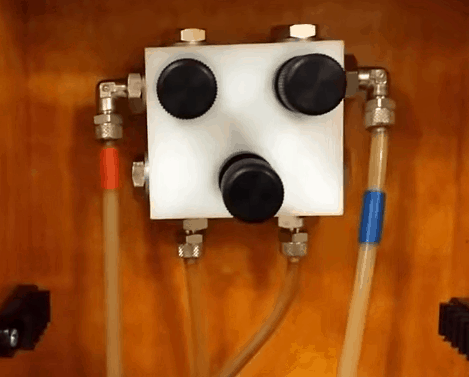
Now we open up the manometer and find the high pressure side which will be coloured red. Ensure that the two top valves to your high and low pressure side are both fully closed, and that the lower, middle, bypass valve is fully open.
Then connect to the red high pressure hose to the red high pressure tube of the orifice plate. You might need to change the connection fitting depending on which valve has been used. You’ll also need to check the threads are all clean, as these are often covered with dust and dirt. Just turn it hand tight and ensure that it isn’t leaking. Lastly, just double check that you’ve connected the correct hose to the correct side.
You should also now check for any pockets of air within the hose or the manometer tubing and flush this out before continuing, as any air pockets will cause inaccuracies with your measurements.
Then locate the blue low pressure hose and connect this to the blue low pressure side of the orifice plate.
Now you’ll need to zero the measurement gauge, so just open up the valve on the high pressure side of the orifice plate as well as the red high pressure valve in the manometer.
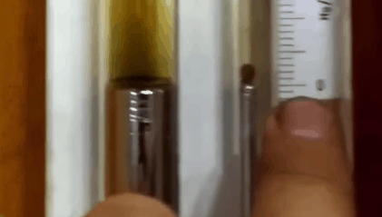
After that, you can then check that the bottom of the little ball within the manometer is level with the zero mark on the gauge.
If it’s not level with this, then you can just move the measurement gauge up or down to align this. Now once you’re happy with the zero alignment, you can then open up the low pressure side of the orifice plate. Sometimes when you open these valves up, they dribble just a little bit. If this happens, then just make the connection a little bit tighter and it will stop. After that, you can then open up the top blue low pressure valve within the manometer. Once that’s fully open, you can then begin to close the middle bypass valve.
When you do this, make sure you close the bypass valve very slowly and watch the little red ball begin to rise, this can suddenly shoot up very fast. If it does get too high towards the top, then you should immediately re-open up the middle bypass valve fully to prevent the mercury from escaping. Once the valve is fully open just leave it a moment to settle down and once it is stable you can then take a measurement.
Note: the little ball will likely move up and down slightly, and that’s just due to the pumps and the turbulent flow within the pipe work. Once you’re happy that it has settled down, you can then take the pressure reading.
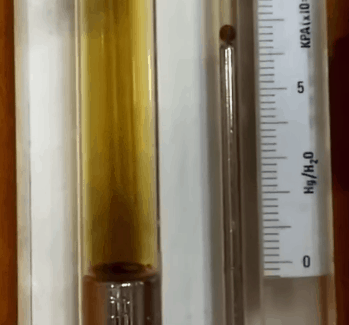
Above, you can see it has a reading of around 6.2 kPa, that’s just the pressure difference between the high and the low side of the orifice plate. So just take a note of the reading and then you can begin to disconnect the equipment.
To do this, just open up the bypass valve and then close the high and low pressure valves within the manometer. After that, you can then close the high pressure valve on the orifice meter and disconnect the hose. Then after that, do exactly the same on the low pressure side of the orifice plate.
So now we can calculate the flow rate. To do this, we first need to know what the KVS value is, this is set by the manufacturer of the orifice plate. The KVS value will vary between manufacturers as well as the model numbers and also the size of the orifice plate. So make sure you use the correct value.
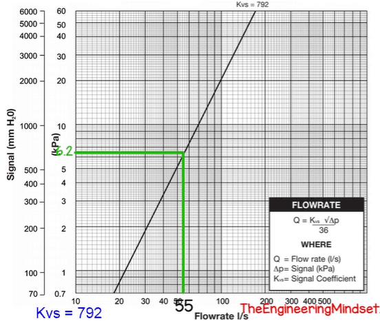
The manufacturer will likely provide a chart which you can use for a quick and easy lookup. To do that, just mark the pressure reading on the chart, which was 6.2 kPa. We just put this on the y-axis, then we can draw a horizontal line across until it hits that dark KVS line.
From there we can then draw another line down vertically, straight down to see what the flow rate is. So here you can see it has a flow rate of around 55 litres per second. But if you want a more precise way, than we can perform a calculation.
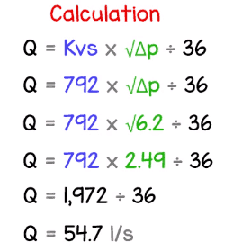
For that we need to use the formula which is the flow rate, Q, is equal to the KVS value multiplied by the square root of the pressure difference, divided by 36. Now we know what our KVS value is, so we can just drop that number in. We also know what the pressure difference value is, too, so we can drop that in, also. Then we just square that value and multiply it by the KVS value. Then we just divide this all by 36 to get the answer of 54.7 litres per second. And there you have it. That is the water flow rate for your chiller.


Hello Paul
Thanks for the help you are providing to the community.
I have a question
I am maintaining an old chiller in which has been retort fitted I don’t have the KVS value for it how do I calculate the flow rate? Please help if you can
If you can find an orifice then uncover it and look for any markings which will lead you to the manufacturer. There should hopefully be a commissioning log book for the system when it was installed, data can be there too. Otherwise you can buy a clamp on flow sensor.
Hi paul
Thanks once again for the help you are giving to the community I appreciate it.
I am working on excel program to produce indirect leaks check calculations and chiller plant performance . soon will be ready if you require a copy let me know
Cheers
Mallek
Great thanks for your guidance in engineering world
Keep that spirit